


MasterCAN DAC connection / Connection using S6 Technology
MasterCAN DAC J1939 i/o modules. Operation manual. Version 2.0
©
Technoton, 2018
25
2.4 Connection using S6 Technology
The connection of
is performed in accordance with the
designation of contacts of
S6
connector and the colour of wires of
Table 8
—
Connection of
S6
connector
Connector
Pinout
Connector
Contact
Number
Wire Marking
Wire Color
Circuit
Designation
Signal
Parameters
1
VBAT
Orange
Power “+”
*
Analog,
voltage
9
…
45 V
2
GND
Brown
Ground “
-
”
—
3
CANH
Blue
CAN HIGH
Digital,
CAN 2.0B,
SAE J1939
Standard
4
CANL
White
CAN LOW
5
KLIN
Black
K-Line
**
Digital,
ISO 14230
Standard
*
To provide power supply for CANCrocodile (only in case of
connection to MasterCAN DAC15).
**
For MasterCAN DAC configuration and firmware update.
ATTENTION:
1)
To ensure correct data transmission via CAN (J1939) communication line in case
of MasterCAN DAC connection to the Telematics terminal that has no inbuilt
terminal resistor,
connect S6 CW plugs
) at both ends of the
communication line between CAN LOW and CAN HIGH wires (see figure 12).
2)
In case of MasterCAN DAC2113 connection, you may enable the inbuilt terminal
resistor in CAN j1939/S6 interface connection settings (see
). In this case, you
must connect S6 CW plug only at that end of the communication line which is
connected to the terminal.
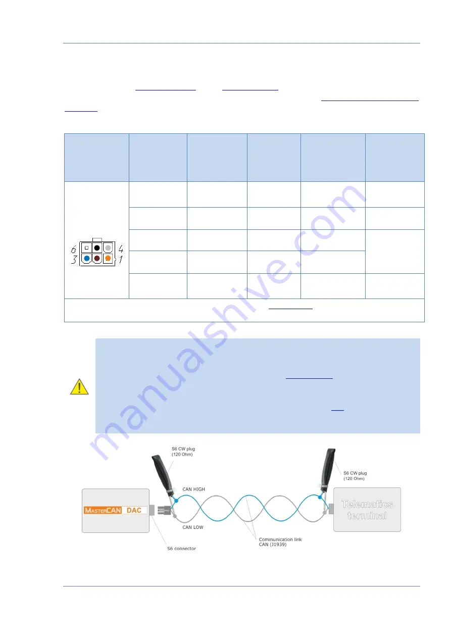
Figure 12
—
Connection of MasterCAN DAC to the Telematics terminal
that has no inbuilt terminal resistor