background image

Technologic Systems, Inc. 

TS-ENC550 - 16


Regulatory Notices 


FCC Advisory Statement 


!


Warning


This equipment generates, uses, and can radiate radio frequency energy and if not installed and 

used properly (that is, in strict accordance with the manufacturer’s instructions), may cause 

interference to radio and television reception. It has been type tested and found to comply with 

the limits for a Class A computing device in accordance with the specifications in Subpart J of 

Part 15 of FCC Rules, which are designed to provide reasonable protection against such 

interference when operated in a commercial environment. Operation of this equipment in a 

residential area is likely to cause interference, in which case the owner at his own expense will 

be required to correct the interference. 
If this equipment does cause interference, which can be determined by turning the unit on and 

off, the user is encouraged to try the following measures to correct the interference: 
1.


Reorient the receiving antenna. 

2.


Relocate the unit with respect to the receiver. 

3.


Plug the unit into a different outlet so that the unit and receiver are on different branch 

circuits. 

4.


Ensure that mounting screws and connector attachment screws are tightly secured. 

5.


Ensure that good quality, shielded, and grounded cables are used for all data 

communications. 

 
If necessary, the user should consult the dealer or an experienced radio/television technician 

for additional suggestions. The following booklets prepared by the Federal Communications 

Commission (FCC) may also prove helpful: 


How to Identify and Resolve Radio-TV Interference Problems

 (Stock No. 004-000-

000345-4) 


Interface Handbook 

(Stock No. 004-000-004505-7) 

 
These booklets may be purchased from the Superintendent of Documents, U.S. Government 

Printing Office, Washington, DC 20402 


Summary of Contents for TS-ENC550

Page 1: ...Enclosure TS ENC550 User Manual 16525 East Laser Drive Fountain Hills AZ 85268 TEL 480 837 5200 FAX 480 837 5400 info embeddedx86 com http www embeddedx86 com...

Page 2: ...Technologic Systems Inc TS ENC550 2 COPYRIGHT 1998 2009 Technologic Systems Inc Enclosure 550 User Manual Rev 1 2 July 2009 Note All modifications from previous versions are listed in Appendix B...

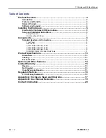
Page 3: ...mponents 6 Standard Headers and Connectors 6 Front Panel 6 Rear Panel 6 COM1 9 Pin SubD Outs Table 8 COM2 9 Pin SubD Outs Table 9 COM3 9 Pin SubD Outs Table 10 DIO ADC COM4 25 Pin SubD Outs Table 11 P...

Page 4: ...connector allows 4th COM port or 8 A D channels or 12 DIO signals to be available at back panel Status LED s for Ethernet ports are visible Power Good LED visible at back panel Reset button recessed...

Page 5: ...al material handling Set the enclosure on a level surface with adequate ventilation Ensure the rubber feet are used for protection and stability on level surfaces Wall mount the unit if placement on a...

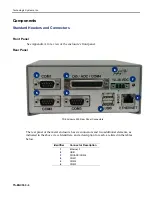
Page 6: ...8 8 3 3 4 4 7 7 5 5 6 6 1 1 2 2 TS Enclosure 550 Rear Panel Connectors The rear panel of the metal enclosure has six connectors and two additional elements as indicated in the above view Identifiers...

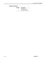
Page 7: ...TS Enclosure 550 User Manual Rev 1 2 TS ENC550 7 Additional Elements Identifier Description 7 7 12 38VDC and Power Indicator LED 8 8 Chassis Grounding Lug...

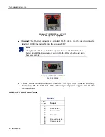
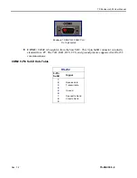
Page 8: ...ates a 100 Mbit link while the left side LED indicates network activity Both LEDs are highlighted red in the above graphic Enclosure TS ENC550 COM1 Port Pin 1 highlighted COM 1 COM1 is brought in from...

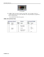
Page 9: ...rought in from the base SBC This 9 pin SubD connector is industry standard for a PC The TxD RxD RTS CTS and ground pins are supported for RS 232 communications COM2 9 Pin SubD Outs Table RS 232 9 Pin...

Page 10: ...d for RS 232 communications See the table below for RS 485 operation COM3 9 Pin SubD Outs Table Half Duplex RS 485 RS 232 Full Duplex RS 485 9 Pin SubD Signal 9 Pin SubD Signal 9 Pin SubD Signal 1 1 R...

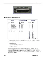
Page 11: ...Terminal Ready 2 24 4 AD6 8 8 DIO7 2 22 2 Ring Indicator 2 25 5 AD7 1 14 4 Ground 1 15 5 DIO8 1 16 6 DIO9 1 17 7 DIO10 1 18 8 DIO11 1 19 9 DIO12 2 20 0 DIO13 2 21 1 5v 250 mA DIO ADC COM4 COM4 for the...

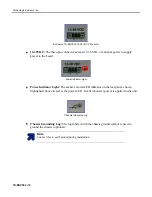
Page 12: ...Power Indicator Light Power Indicator Light The amber colored LED indicator on the rear panel shown highlighted above in red is the power LED It is lit whenever power is applied to the unit Chassis G...

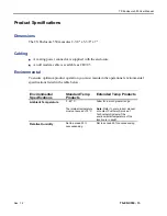
Page 13: ...must maintain the operational environmental specifications listed in the table below Environmental Specifications Standard Temp Products Extended Temp Products Ambient Temperature 0 60 C The internal...

Page 14: ...Technologic Systems Inc TS ENC550 14 Options and Other Features RS 485 is optional on COM3 A wall mounted power supply is available for this product...

Page 15: ...conditions of operation or attempts to alter or modify the function of the product i Important This warranty is limited to the repair or replacement of the defective unit In no event shall Technologi...

Page 16: ...does cause interference which can be determined by turning the unit on and off the user is encouraged to try the following measures to correct the interference 1 Reorient the receiving antenna 2 Relo...

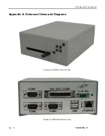
Page 17: ...TS Enclosure 550 User Manual Rev 1 2 TS ENC550 17 Appendix A Enclosure Views and Diagrams Enclosure TS ENC550 Front Top View Enclosure TS ENC550 Rear Panel View...

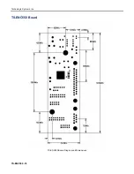
Page 18: ...Technologic Systems Inc TS ENC550 18 TS ENC550 Board TS ENC550 Board Diagram and Dimensions...

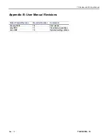
Page 19: ...ser Manual Rev 1 2 TS ENC550 19 Appendix B User Manual Revisions Date of Issue Revision Revision Number Comments January 2005 July 2008 June 2009 1 2 Updated mailing address 1 0 1 1 First release Fixe...

Page 20: ...Technologic Systems Inc TS ENC550 20 Contact Information 16525 East Laser Drive Fountain Hills AZ 85268 TEL 480 837 5200 FAX 480 837 5400 info embeddedx86 com http www embeddedx86 com...

Reviews: