background image

TS Enclosure 530 User Manual 

Rev. 1.

2


TS-ENC530 - 5


Installing the Enclosure 

Electrostatic Discharge (ESD) precautions 

Before performing any set up or placement procedures, take the precautions outlined in this 

section. 


Important 

Be sure to take appropriate Electrostatic Discharge (ESD) precautions. 


Disconnect the power cable at the rear panel of the enclosure before moving, 

cabling, or performing any set up procedures. 


Setup and Installation Instructions 

Follow these guidelines for safety and maximum product performance: 


Observe local health and safety requirements and guidelines for manual material handling. 


Set the enclosure on a level surface with adequate ventilation. 


Ensure the rubber feet are used for protection and stability on level surfaces. 


Wall-mount the unit if placement on a level surface is not available, or desired. 


Setup Tools 

Depending on the placement and cabling of the enclosure, you may need the following tools: 


Small flat-blade screwdriver 


Small Phillips screwdriver 

Setup Procedure 

After locating, setting up, grounding, and cabling the enclosure: 
1.


Apply power to the unit. 
The amber-colored LED on the rear panel should be lit. 

2.


Monitor COM2 using a terminal emulator to verify that the enclosure is operating 

properly. 

Disconnecting AC Power 

1.


Unplug the power cord from the power source. 

2.


Disconnect the power cord from the rear panel of the enclosure.  


Summary of Contents for TS-ENC530

Page 1: ...Enclosure TS 530 User Manual 16525 East Laser Drive Fountain Hills AZ 85268 TEL 480 837 5200 FAX 480 837 5300 info embeddedx86 com http www embeddedx86 com...

Page 2: ...Technologic Systems Inc TS ENC530 2 COPYRIGHT 1998 200...

Page 3: ...p Procedure 5 Disconnecting AC Power 5 Components 6 Standard Headers and Connectors 6 Front Panel 6 Rear Panel 6 COM1 9 Pin SubD Outs Table 7 COM2 9 Pin SubD Outs Table 8 Product Specifications 10 Dim...

Page 4: ...gulator efficiently converts 12 38 VDC to regulated 5 VDC required by the SBC COM ports adapted to standard 9 pin Sub D Status LED s for Ethernet port are visible Power Good LED visible on the rear pa...

Page 5: ...al material handling Set the enclosure on a level surface with adequate ventilation Ensure the rubber feet are used for protection and stability on level surfaces Wall mount the unit if placement on a...

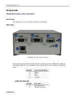
Page 6: ...losure 530 Rear Panel Connectors The rear panel of the metal enclosure has four connectors and two additional elements as indicated in the above view Identifiers and a description for each are listed...

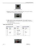
Page 7: ...pin SubD connector is industry standard for a PC The TxD RxD RTS CTS and ground pins are supported for RS 232 communications See the table below for RS 485 operation COM1 9 Pin SubD Outs Table Half Du...

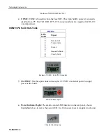
Page 8: ...RS 232 9 Pin SubD Signal 1 1 2 2 Receive data 3 3 Transmit data 4 4 5 5 Ground 6 6 7 7 Request to Send 8 8 Clear to Send 9 9 Enclosure TS 530 12 38 VDC Connector 12 38VDC The three pin connector accep...

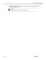
Page 9: ...closure 530 User Manual Rev 1 2 TS ENC530 9 Chassis Grounding Lug The lug labeled with the chassis ground symbol is used to ground the chassis optional Note Connect this to earth ground during install...

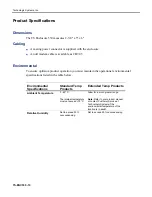
Page 10: ...intain the operational environmental specifications listed in the table below Environmental Specifications Standard Temp Products Extended Temp Products Ambient Temperature 0 60 C The internal tempera...

Page 11: ...TS Enclosure 530 User Manual Rev 1 2 TS ENC530 11 Options and Other Features RS 485 is optional on COM1 A wall mounted power supply is available for this product...

Page 12: ...ions of operation or attempts to alter or modify the function of the product i Important This warranty is limited to the repair or replacement of the defective unit In no event shall Technologic Syste...

Page 13: ...ipment does cause interference which can be determined by turning the unit on and off the user is encouraged to try the following measures to correct the interference 1 Reorient the receiving antenna...

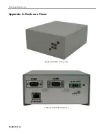
Page 14: ...Technologic Systems Inc TS ENC530 14 Appendix A Enclosure Views Enclosure TS 530 Front Top View Enclosure TS 530 Rear Panel View...

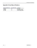
Page 15: ...User Manual Rev 1 2 TS ENC530 15 Appendix B User Manual Revisions Date of Issue Revision Revision Number Comments July 2004 July 2008 June 2009 1 2 Updated mailing address 1 0 1 1 First release Fixed...

Page 16: ...Technologic Systems Inc TS ENC530 16 16525 East Laser Drive Fountain Hills AZ 85268 TEL 480 837 5200 FAX 480 837 5300 info embeddedx86 com http www embeddedx86 com...

Reviews: