Technogym Step 500i Service Maintenance Manual Download Page 177

STEP EXCITE: Service & maintenance manual - rev. 1.4 


Page 10.5 

10.4. 


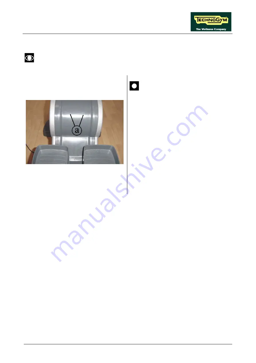
LUBRICATION OF THE PEDALS CHAINS 

  This operation should be carried out whenever the following message appears on the 

display “LUBRICATES THE CHAINS, THEN PRESSES A KEY TO CONTINUE”. 


Figure 10.4-1 


WARNING: to carry out this 
operation, use only the lubricating oil 
supplied with the machine. 

 
1.


Insert the sprayer tube all the way into one 
of the two holes 

a

 and spray the oil. 

2.


Using one foot, slowly push down the pedal 
corresponding to the hole and continue 
spraying. 

3.


Remove the sprayer tube and slowly allow 
the pedal to come up. 

 
Repeat the operations on both pedals of the 
machine. 
 
After carrying out the above-described 
operations, change the value of the parameter 
described in paragraph 9.1.16. “Lubricated”. 


Summary of Contents for Step 500i

Page 1: ...SERVICE MAINTENANCE MANUAL REV 1 4...

Page 2: ......

Page 3: ...PRESENT NOTE The information contained in this document is subject to change without notice Technogym does not guarantee this documentation in any way Technogym shall not be held responsible for any...

Page 4: ......

Page 5: ...2 7 4 2 Cordless version 2 12 2 7 5 700iE WTV model 2 13 2 7 5 1 Wellness TV Touch screen NCB version 2 13 2 7 5 2 Wellness TV Touch screen UB version 2 14 2 8 WIRING 2 15 3 PRINCIPLES OF OPERATION 3...

Page 6: ...HE RADIO DOES NOT PLAY 6 16 6 6 THE EQUIPMENT IS BLOCKED MESSAGE ON DISPLAY 6 18 6 7 ERROR DETECTED BY BRAKE BOARD 6 19 6 7 1 Brake board error 1 6 19 6 7 2 Brake board error 8 6 19 6 8 THERE IS NO RE...

Page 7: ...IGN THE PULLEY AND BELT 8 6 8 7 LEVELLING 8 7 9 MACHINE CONFIGURATION 9 1 9 1 USER MENU CONFIGURATION FOR 700 MODELS 9 1 9 1 1 Language 9 1 9 1 2 Distance 9 2 9 1 3 Priority setting 9 2 9 1 4 Maximum...

Page 8: ...9 22 9 3 12 TV Standard 700i E version only 9 22 9 3 13 Screen saver 9 23 9 3 14 Waiting time 9 24 9 4 TV MENU CONFIGURATION FOR 700I E MODELS 9 25 9 4 1 Tuning TV channels 9 25 9 4 2 Wellness TV adju...

Page 9: ...Checking the belt 10 3 10 3 6 Checking the chains 10 3 10 3 7 Checking the wear of the pulleys 10 3 10 3 8 Checking the play of the lever and pedal group 10 4 10 3 9 Checking the display 10 4 10 3 10...

Page 10: ...STEP EXCITE Service maintenance manual rev 1 4 Pagina vi Page intentionally left blank...

Page 11: ...on observance may cause damage to the machine Information about the operation in progress OBSERVE observation about the operation in progress 1 2 RECOMMENDATIONS Technogym recommends the following ste...

Page 12: ...recommended brands 3 Use special tools where specified 4 Consult the Technical Newsletters which may contain more up to date information on adjustments and maintenance than those contained in this man...

Page 13: ...ply 3 multi voltage 110 220 4 self powered 6 Type of display L LED display E Wellness TV 7 Device for downloading data used by the Wellness System N not available T TGS 8 9 Color of the frame AL alumi...

Page 14: ...ilable in 5 versions Step 500i mains operated machine Step 500i SP self powered machine Step 700i mains operated machine Step 700i SP self powered machine Step 700i E mains operated machine with Welln...

Page 15: ...Width 79 cm 31 1 in Length 112 cm 44 1 in Height 184 cm 72 4 in Weight 100 kg 220 lbs 2 4 ELECTRICAL CHARACTERISTICS VERSION 500I 700I 700I E Europe Asia 90 260 VAC Mains voltage USA Canada 90 130 VA...

Page 16: ...3 3 Safety EN 60335 1 EN 957 1 EN 957 8 class SA Directives 73 23 CE 89 366 CE 98 37 CE UL 1647 In addition Electrical isolation class Class I mains operated machine Class II self powered machine Pro...

Page 17: ...I MODEL 2 7 1 1 Powered version BRAKE POWER ENTRY MODULE VAC BRAKE BOARD CN3 CN4 CN1 CN2 SPEED SENSOR STP 00 Patch Conn DISPLAY DISPLAY BOARD CBQ 32 KEYBOARD 386 BOARD CN7 TGS READER CN1 CN9 CN1 CN2 C...

Page 18: ...ess version DISPLAY DISPLAY BOARD CBQ 13 CBQ 32 CSAFE BOARD 386 BOARD HFU RECEIVER CN7 CN8 CN1 TGS BOARD CN1 CN9 CN1 CN3 CN2 ELT 16 BRAKE BRAKE BOARD CN3 CN4 CN1 CN2 NTC Patch Conn STP 05 STP 04 STP 0...

Page 19: ...BOARD 2 7 2 1 Powered version BRAKE POWER ENTRY MODULE VAC BRAKE BOARD CN3 CN4 CN1 CN2 SPEED SENSOR STP 00 Patch Conn DISPLAY ARM DISPLAY BOARD CBQ 32 KEYBOARD CN7 TGS READER CN1 CN9 CN1 CN2 CBQ 13 CS...

Page 20: ...dless version DISPLAY ARM DISPLAY BOARD CBQ 13 CBQ 32 CSAFE BOARD HFU RECEIVER CN7 CN8 CN1 TGS READER CN1 CN9 CN1 CN3 CN2 ELT 16 BRAKE BRAKE BOARD CN3 CN4 CN1 CN2 NTC Patch Conn STP 05 STP 04 STP 03 B...

Page 21: ...D CSAFE BOARD 386 BOARD HFU RECEIVER CN7 CN8 CN1 TGS READER CN1 CN9 CN1 CN3 CN2 ELT 16 BRAKE POWER ENTRY MODULE VAC BRAKE BOARD CN3 CN4 CN1 CN2 SPEED SENSOR STP 00 Patch Conn STP 04 STP 03 CN4 CBQ 25...

Page 22: ...TOR Patch conn STP 01 BATTERY CHARGER INPUT DISPLAY HAND SENSOR BOARD DISPLAY BOARD CBQ 13 CBQ 32 KEYBOARD CSAFE BOARD 386 BOARD HFU RECEIVER CN7 CN8 CN1 TGS READER CN1 CN9 CN1 CN3 CN2 ELT 16 STP 04 S...

Page 23: ...Q 32 KEYBOARD CSAFE BOARD HFU RECEIVER CN7 CN8 CN1 TGS READER CN1 CN9 CN1 CN3 CN2 ELT 16 BRAKE POWER ENTRY MODULE VAC BRAKE BOARD CN3 CN4 CN1 CN2 SPEED SENSOR STP 00 Patch Conn STP 04 STP 03 CN4 CBQ 2...

Page 24: ...RNATOR Patch conn STP 01 BATTERY CHARGER INPUT DISPLAY HAND SENSOR BOARD ARM DISPLAY BOARD CBQ 13 CBQ 32 KEYBOARD CSAFE BOARD HFU RECEIVER CN7 CN8 CN1 TGS READER CN1 CN9 CN1 CN3 CN2 ELT 16 STP 04 STP...

Page 25: ...J1 BRAKE POWER ENTRY MODULE VAC BRAKE BOARD CN4 CN3 CN1 CN2 SPEED SENSOR STP 00 Patch Conn STP 04 STP 03 CN11 CN19 J2 J8 CSAFE BOARD CN1 CBQ 13 CB 9 CONNECTORS PANEL Antenna inlet J1 STP 07 CU40 CN1...

Page 26: ...PUT BOARD J2 CN1 Right CB 9 CONNECTORS PANEL Antenna intel J7 STP 07 RIGHT HEADPHONE JACK Pach Conn CU82 J3 CN27 CN26 ELT 16 HAND SENSOR BOARD J3 J2 J4 L UPPER SENSOR R LOWER SENSOR L LOWER SENSOR R U...

Page 27: ...hing White 8 CBQ 13 CSafe board cable Display Board CSafe Board Display Board CN8 Signal Color CSafe Board CN1 1 Digital 1 Flat cable 1 14 Digital 14 Flat cable 14 CBQ 25 1 Hand sensor board cable Dis...

Page 28: ...8 Gnd Green 1 STP 00 High voltage cable Power entry module Brake board Power entry module Signal Color Brake board CN3 F Line White 1 N Neutral Brown 3 T Earth Green 5 STP 01 Alternator cable Brake bo...

Page 29: ...e between upper and lower assemblies Brake board Display Board Brake board CN4 Signal Color Display Board CN9 1 Digital Gnd Orange White 1 2 Digital Gnd Orange 2 3 NC Green White 3 4 Download Blue 4 5...

Page 30: ...ard Sensors J2 J4 Signal Color Right Left 1 Right sensor signal White up 2 Sensor signal reference Brown down 3 Gnd Black 4 Left sensor signal White up 5 Sensor signal reference Brown down 6 Gnd Yello...

Page 31: ...ION POWER ENTRY MODULE DISPLAY DISPLAY BOARDS CSAFE BOARD TGS READER BRAKE BOARD CARDIO RECEIVER VAC CONNECTORS PANEL NET Antenna inlet W TV only KEYBOARD TOUCH SCREEN W TV only RIGHT TOUCH SENSORS LE...

Page 32: ...als received from Keyboard Cardio receiver TGS reader CSafe Board distributes the voltages received from the Brake board to the display exchanges via the RS 485 serial link to the Brake board the comm...

Page 33: ...the LEDs and the 7 segment displays which provide feedback about the exercise session The board includes the following indicator LEDs LED name Color Description LED1 yellow if ON the 5 Vdc power suppl...

Page 34: ...ion JP1 open if closed resets the board JP2 closed if closed allows the backup battery to keep the system clock active 3 1 1 4 700i ARM and 700i SP ARM models The display comprises the following circu...

Page 35: ...oard AUX video input board Antenna signal Power supplies from the Brake board RS 485 serial link with the brake Touch sensor It has a connector linking it to the CPU board for transferring the collect...

Page 36: ...only one board which carry out all the functions previously done by the connectors board and CPU board It is the circuit board which incorporates the CPU its control logic the FLASH EPROM containing...

Page 37: ...his is the board that controls the 4 wire resistive Touch Screen and interfaces the Touch Screen to the CPU board AUX INPUT BOARD This board provides 3 RC connectors and one mini DIN connector for int...

Page 38: ...rs monitors motors etc within this area the receiver becomes saturated and no longer receives any signal 3 1 6 CONNECTORS PANEL This is located on the side of the front platform and provides a connect...

Page 39: ...it detects a temperature exceeding 140 C 3 1 9 SPEED SENSOR Only for 500i 700i and 700i E versions This consists of a magnetic induction sensor which detects the heads of the brake disk fixing screws...

Page 40: ...as a built in speed sensor which provides to the brake board the speed signal 3 1 13 BATTERY Only for 500i SP and 700i SP versions This is a 12 V 4 5 AH battery which in the self powered version suppl...

Page 41: ...LS The control block diagram is as follows To obtain a given exercise effort level the display board sends the required value of exercise speed in step per minute to the Brake board via the RS 485 ser...

Page 42: ...n occur are Error Code Description 1 OVERHEATING this condition occurs when the temperature detected by the sensor on the circuit board exceeds 90 C 8 OVERVOLTAGE this condition occurs when the 12 Vdc...

Page 43: ...pins 3 4 on connector CN2 where it is used to determine the speed value that is sent to the display board via the RS 485 serial link This signal can also be measured qualitatively using a multimeter T...

Page 44: ...STEP EXCITE Service maintenance manual rev 1 4 Page 3 14 Page intentionally left blank...

Page 45: ...er cable having the following pin out RJ45 Connector Signal 5 5 Vdc 7 Ground ATTENTION for the numbering of the pins on RJ45 connector please refer to the diagram below 4 2 PC LINK FOR PROGRAMMING The...

Page 46: ...ode H0002534AA 4 3 CABLE FOR EXCHANGING TV CHANNEL TUNING DATA BETWEEN TWO MACHINES The link for transferring the TV channel tuning data from one machine to the other is effected via a special cable w...

Page 47: ...nto any one of the CSafe ports on the machine the corresponding LED should illuminate to indicate the presence of the 5 Vdc supply on the port During the CSafe port test function the plug connects the...

Page 48: ...lgium Cameroon Croatia Cyprus Czech Rep Denmark Finland Germany Ghana Greece Hungary India Israel Italy Jordan Kenya Luxembourg Malaysia Malta Netherlands New Zealand Nigeria Norway Pakistan Poland Po...

Page 49: ...rade kit consists of 1 External connector board cover plate cod 0C000550AB 2 External connector board cod 0WQ00115AC 3 Self tapping screws 5x14 cod 0Z775 4 Self tapping screws 3 5x6 cod 0Z7018 5 Washe...

Page 50: ...from the wall outlet 2 Back off the 4 screws a using a medium Phillips screwdriver Figure 4 5 4 3 Unplug the connectors indicated in the figure 4 Remove the display Figure 4 5 5 5 Turn the machine ove...

Page 51: ...rting the washer as shown in the figure Figure 4 5 8 10 Insert cable 8 STP_07 into hole e and bring it out from the top of the machine If the cable doesn t pass trough the machine frame use a cable pu...

Page 52: ...pecial guides on cover plate 1 in such a way that the connectors on the board match up with the holes on the cover plate 16 Secure external connector board 2 with screws and washers 4 and 5 using a Ph...

Page 53: ...ews h 22 Connect the following cables to the WTV display Cable 8 STP_07 on connector j1 of the connector board All the connectors previously disconnected from the display in step 3 The TGS cable if pr...

Page 54: ...STEP EXCITE Service maintenance manual rev 1 4 Page 4 10 Page intentionally left blank...

Page 55: ...Only for 500i 700i and 700i E models 6 The mains voltage must match the value specified on the machine rating plate 7 The electrical system must be correctly earthed 8 The wall outlet used should be...

Page 56: ...re the machine is ready for use On the 500i 700i and 700i E models simply turn the on off switch from position 0 to position 1 while on the 500i SP and 700i SP models it is necessary to get on the mac...

Page 57: ...response This type of box is a step in the troubleshooting procedure where an ACTION must be carried out It typically contains a description of the ACTION necessary to resolve the problem Therefore a...

Page 58: ...there are two options available Tech Config Troubleshooting Press numeric key to access the menu for configuring technical parameters the machine display will begin showing the current configuration s...

Page 59: ...g the desired test using the and effort level keys press ENTER to initiate the test and then await the result Press ENTER again to continue and use the CLEAR key to return to the higher menu level hol...

Page 60: ...TGS COM test The TGS COM test done on machine not provided with the key reader gives a fail outcome The same if the CSafe COM test is done on a machine which CSafe port is not plugged with the monitor...

Page 61: ...00I AND 700I MODELS Does the wall outlet supply the correct voltage Is the mains lead OK Is the voltage at the output of the machine s power entry module correct Plug the machine into a working electr...

Page 62: ...ghlighted by circled numbers which are described in detail below To speed up the troubleshooting procedure check the state of the power indicator LEDs on the various circuit boards 1 Slightly lift up...

Page 63: ...operation af ter 30 seconds without do the exercise the machine switches of f Replace the alternator Replace cable STP 01 or the f use in the same cable THE DISPLAY DOES NOT ILLUMINATE NO YES NO YES...

Page 64: ...tays on for 30 seconds after having stopped pedalling If the machine switches off in few seconds check if the fuse on the STP 01 cable is blown 2 Place the tester probes across the ends of the cable f...

Page 65: ...of the machine s power entry module correct Plug the machine into a working electrical outlet Replace the mains lead Replace the power entry module on the machine THE DISPLAY DOES NOT ILLUMINATE Does...

Page 66: ...lace cable STP 03 NO YES 4 Are the DC voltages at the output of the CPU board to the LCD inverter correct NO 5 Replace the CPU and or connector board YES Are the DC voltages at the input to the LCD in...

Page 67: ...described in detail below To speed up the troubleshooting procedure check the state of the power indicator LEDs on the various circuit boards 1 Place the tester probes across the ends of the cable com...

Page 68: ...manual rev 1 4 Page 6 12 6 As for step 3 but on connector CN1 of the LCD inverter 7 Place the tester probes across the two pins of connectors CN2 and CN3 on the LCD inverter board The measured value...

Page 69: ...er NO YES NO AUDIO SOUND 1 Replace the headphone jack Does it work Def ective headphone jack YES NO Try replacing the CPU Does it work Def ective CPU board YES Replace the CPU board NO Follow the proc...

Page 70: ...V PICTURE YES 3 The signal derived f rom the video signal is insuf f icient Contact the system administrator NO Disconnect the splitter and connect the tuner directly to an antenna cable Does it work...

Page 71: ...uration procedure described in paragraph 9 3 12 TV Standard 700i E version only 3 For models with European electronics unplug the antenna cable from the connector board and plug it into the tuner whil...

Page 72: ...ork procedure Def ective CPU board NO YES THE RADIO DOES NOT PLAY YES 1 The signal derived f rom the video signal is insuf f icient Contact the system administrator NO Disconnect the splitter and conn...

Page 73: ...anual rev 1 4 Page 6 17 1 After disconnecting the splitter from the tuner procure a female RC connector and a copper wire about 1 5 m long Connect the copper wire to the tuner through the RC connector...

Page 74: ...eshooting procedure YES 2 3 Follow the procedure step by step to correctly diagnose the problem Take particular care with the checks highlighted by circled numbers which are described in detail below...

Page 75: ...ARD Check the error code stored in memory Error 8 Error 1 The following paragraphs describe the troubleshooting procedures for these cases 6 7 1 BRAKE BOARD ERROR 1 This code indicates an overheating...

Page 76: ...the SPM value is incorrect troubleshooting procedure Replace the brake board YES Does the brake winding receive current f rom the brake board NO Replace the brake winding YES Replace cable ELT 02 NO 2...

Page 77: ...he brake winding YES THE RESISTANCE IS INCORRECT 1 Repair the f aulty mechanical parts NO Carry out the Speed is Incorrect troubleshooting procedure YES Follow the procedure step by step to correctly...

Page 78: ...r generator NO SW not correctly loaded YES Is the brake disk correctly f ixed to the f lywheel THE SPEED IS INCORRECT 1 Fix it correctly NO YES Check if the parameters conf iguration is right Is the s...

Page 79: ...uld be 136 Hz Self Powered models Check the signal on the STP 01 cable referring to paragraph 2 8 Wiring The measured signal should be that indicated in Figure 3 2 1 In addition when pedaling at 80 SP...

Page 80: ...t the output to the display board correct Replace cable CBQ 32 1 2 YES NO YES Replace the display board NO A Is the serial communication link between the display board and the TGS reader OK Replace th...

Page 81: ...tester probes across pins 1 and 3 of connector CN1 of the TGS reader The measured value should be 12 Vdc 2 As for step 1 but across pins 1 and 9 of connector CN7 on the display board 3 Use the serial...

Page 82: ...s the supply voltage correct at the output of the display board Replace the receiver Replace CBQ 28 cable 2 3 YES NO YES Replace display board NO Carry out the troubleshooting procedure THE TELEMETRIC...

Page 83: ...einstate the connection Replace cable CBQ 25 1 Replace the display board 2 4 YES NO YES NO Is the supply voltage correct at the input to the HS interface board Replace the HS interf ace board 3 YES NO...

Page 84: ...Check the connections referring to paragraph 2 8 Wiring 3 Place the tester probes across pins 2 and 1 of connector J3 on the HS interface board The measured value should be 5 Vdc 4 As for step 2 but...

Page 85: ...the required minimum distance Is the receiver correctly positioned and are the connecting cables properly routed Are there sources of electromagnetic noise near the receiver Reposition the machines so...

Page 86: ...e described in detail below 1 Check the earthing of the machine using a tester to measure the resistance between the ground pin on the power supply cable and the ground node to which the receiver is c...

Page 87: ...lowing cables ELT 16 0WC00518AB CBQ 28 0WC00390AC or TRM 28 0WC00336AC as connection cable The circuit lights the LED for each heart beat and or disturbance received in this way it is possible to dete...

Page 88: ...STEP EXCITE Service maintenance manual rev 1 4 Page 6 32 Page intentionally left blank...

Page 89: ...machine and unplug the mains lead from the wall outlet 2 Back off the 4 screws a using a medium Phillips screwdriver Figure 7 1 2 3 Unplug the connectors indicated in the figure at left 4 Remove the...

Page 90: ...the wall outlet 2 Back off the 4 screws a using a medium Phillips screwdriver Figure 7 1 5 3 Unplug the cables indicated in the figure from the connector board and the CSafe board 4 Remove the display...

Page 91: ...ead from the wall outlet 2 Back off the 4 screws a using a medium Phillips screwdriver Figure 7 1 8 3 Unplug the connectors indicated in the figure at left 4 Remove the display Figure 7 1 9 5 Back off...

Page 92: ...boards The 386 board a The display board b The CSafe board c Figure 7 2 2 386 board a 1 Remove the hot glue and release the fixing tabs The board will lift up slightly 2 Extract it from the connector...

Page 93: ...4 Page 7 5 Figure 7 2 4 To remove the hand sensor board 1 Unplug the 2 connectors indicated in the figure 2 Release the 3 clips e and remove the hand sensor board To reassemble the electronics boards...

Page 94: ...on a work bench It is now possible to disassemble its circuit boards The CSafe board a The LCD inverter b The connector board c The CPU board d The Touch Screen interface board e Figure 7 2 6 CSafe Bo...

Page 95: ...3 Remove the circuit board from the display taking care not to damage the connector that attaches it to the CPU board Figure 7 2 10 CPU Board d 1 Disassemble the connector board 2 Unplug the cables in...

Page 96: ...h screen interface board to the TTL board and to the LCD on the inverter indicated in the figure 2 Back off the 6 screws p securing the plate and all the display boards to the front cover 3 To unplug...

Page 97: ...ch It is now possible to disassemble its circuit boards The LCD inverter a The CPU board b Figure 7 2 15 LCD inverter b 1 Back off the two screws c using a Phillips screwdriver 2 Raise the inverter co...

Page 98: ...nplug the connectors of the cables leading from the touch screen to the TTL board and to the LCD on the inverter indicated in the figure To unplug the cable from the TTL board open the connector on th...

Page 99: ...re 7 2 21 9 Shift on one side the touch screen s paying attention to its cable 10 Back off the 4 screws t using a small Phillips screwdriver 11 Lift up and remove the LCD Figure 7 2 22 To disassemble...

Page 100: ...ge 7 12 Figure 7 2 23 To remove the hand sensor board 1 Unplug the 2 connectors indicated in the figure 2 Release the 3 clips t and remove the hand sensor board To reassemble the circuit boards and th...

Page 101: ...e CSafe board c Figure 7 2 25 386 board a 1 Release the fixing tabs The circuit board will lift up slightly 2 Remove it from the connector on the display board display board b 1 Unplug the keyboard co...

Page 102: ...a corner of the keyboard To assemble a new keyboard with the display on a work bench 1 Remove the backing film from the adhesive 2 Apply the adhesive part starting from the left and working toward the...

Page 103: ...cure the plate and all the display circuit boards to the front cover Figure 7 3 4 3 Back off the 2 screws b securing the headphone jack to the display using a small Phillips screwdriver 4 Unplug the c...

Page 104: ...STEP EXCITE Service maintenance manual rev 1 4 Page 7 16 Figure 7 3 6 8 Lift up and replace the touch screen d To reassemble the keyboard carry out the above steps in reverse order...

Page 105: ...keyboard To assemble a new keyboard with the display on a work bench 1 Remove the backing film from the adhesive 2 Apply the adhesive part starting from the left and working toward the right without b...

Page 106: ...unplug the mains lead from the wall outlet 2 Back off the 6 screws a using a medium Phillips screwdriver 3 Lift up the upper tray bracket Figure 7 4 2 4 Remove the adhesive tape 5 Remove the cardio r...

Page 107: ...and the connector c Figure 7 4 5 2 Connect the cable to the cardio receiver and bend the cable on a side of the connector Figure 7 4 6 3 Place the receiver in the sponge d as shown in the picture to...

Page 108: ...ervice maintenance manual rev 1 4 Page 7 20 Figure 7 4 7 5 Place the sponge and the receiver in the plastic housing as shown in the picture Figure 7 4 8 6 Secure the cardio receiver and the sponges wi...

Page 109: ...ne and unplug the mains lead from the wall outlet 2 Back off the 6 screws a using a medium Phillips screwdriver 3 Remove the upper tray Figure 7 5 2 4 Back off the 4 screws b using a 4 mm hex wrench 5...

Page 110: ...g a torque wrench setting of 30 Nm Figure 7 5 5 To disassemble all parts of the handlebar 1 Back off the 2 screws e using a 6 mm hex wrench During reassembly lock down the screws e using a torque wren...

Page 111: ...unplug the mains lead from the wall outlet For each sensor 1 Back off the 2 screws a using a medium Phillips screwdriver Figure 7 6 2 2 Lift up the top sensor 3 Remove the lower sensor 4 To remove th...

Page 112: ...eassembly insert the longer screw in the position indicated by the arrow During reassembly lock down the screws a using a torque wrench setting of 2 Nm 2 Remove the lateral guards Figure 7 7 2 To disa...

Page 113: ...4 To disassemble the drip flat f 7 Push the drip flat f toward the crown wheel as far as the plastic pin highlighted in the figure comes out of the machine frame 8 Remove the drip flat from the top T...

Page 114: ...embling the guards 2 Back off the screw a using a medium Phillips screwdriver 3 Remove the cover plate from the electrical box Figure 7 8 2 4 Unplug the 4 connectors indicated in the figure at left 5...

Page 115: ...screws a using a medium Phillips screwdriver 2 Remove the pedal During reassembly lock down the screws a using a torque wrench setting of 2 5 Nm To reassemble the pedals carry out the above steps in r...

Page 116: ...the lever using a 5 mm hex wrench 5 Back off the snap ring c using the proper pliers Figure 7 10 3 6 Using an 8 mm hex wrench back off the screw d securing the joint connected to the chain onto the ma...

Page 117: ...dal levers carry out the above steps in reverse order Before re inserting the lever on the pins as shown in the figure remember to insert the lock washer e Figure 7 10 5 To re insert the lever align t...

Page 118: ...m the winding 2 Unplug the connector circled in the figure at left Figure 7 11 2 3 Back off the 2 screws b using an 17 mm wrench supporting the entire brake winding group c to avoid damaging the coppe...

Page 119: ...pin a on the frame of the machine Figure 7 12 2 2 Back off the nut b of the belt tensioning mechanism using a 17 mm hex wrench 3 Back off the grub screw c using a 5 mm hex wrench in order to decrease...

Page 120: ...disk as it bends easily and may then cause problems after reassembly by brushing against the winding block During reassembly lock down the screws e using a torque wrench setting of 6 Nm Figure 7 12 6...

Page 121: ...On the right side of the machine 3 Back off the screw b using a 6 mm hex wrench and release the pin d from the plate c as shown in the figure 4 Remove the winding assembly taking care not to damage th...

Page 122: ...11 2 Remove the stator h from flywheel assembly Figure 7 12 12 3 Back off the 3 screws i using a 4 mm hex wrench and separate the winding from the plastic protection To reassemble the flywheel assembl...

Page 123: ...the bridge bearing and on the machine frame to assist in subsequent reassembly 2 Back off the 2 screws a using a 19 mm wrench 3 Remove the belt by lifting the right part of the bearing Figure 7 13 2...

Page 124: ...7 7 Disassembling the guards 1 Remove the spring from the pin a on the frame of the machine Figure 7 14 2 2 Back off the 4 screws b using a 19 mm wrench 3 Remove the primary shaft assembly from the ch...

Page 125: ...wheel Figure 7 14 6 To remove the crown wheel 1 Back off the 6 screws h using a 5 mm hex wrench locking down the nut on the opposite side of the wheel by using a 10 mm wrench To reassemble the seconda...

Page 126: ...ssembling the electrical box 1 Remove the spring from the pin a on the frame of the machine Figure 7 15 2 2 Back off the nut b of the belt tensioning mechanism using a 17 mm wrench 3 Back off the scre...

Page 127: ...ack off the screw g using a 5 mm hex wrench and its counter nut h 10 Remove the pinion pulley from the shaft To reassemble the secondary shaft assembly carry out the above steps in reverse order Durin...

Page 128: ...2 Remove the speed sensor and its support Figure 7 16 2 3 Cut the cable tie b 4 Unplug the faston indicated in the figure 5 Back off the screw c using a small Phillips screwdriver and remove the eyel...

Page 129: ...ws a using a small Phillips screwdriver 2 Remove the wheels group To remove the power entry module 1 Back off the screws b using a small Phillips screwdriver 2 Remove the power entry module plate cove...

Page 130: ...s to remove the power entry module 3 Back off the 2 screws e using a 17 mm wrench and remove the front platform Figure 7 18 2 To disassemble the rear platform 1 Turn the machine over on one side 2 Bac...

Page 131: ...19 DISASSEMBLING THE BATTERY Figure 7 19 1 Carry out the operations described in paragraph 7 7 Disassembling the guards 1 Cut the strip tie a 2 Unplug the two faston b and remove the battery To reasse...

Page 132: ...STEP EXCITE Service maintenance manual rev 1 4 Page 7 44 Page intentionally left blank...

Page 133: ...on the frame of the machine Figure 8 1 2 Working on the belt tensioning mechanism 2 Back off the lock nut b using a 17 mm wrench 3 Make the adjustment by turning the screw c with a 5 mm hex wrench 4 T...

Page 134: ...D SENSOR POSITION Figure 8 2 1 Carry out the operations described in paragraph 7 7 Disassembling the guards 1 Back off the 2 screws a and shift the speed sensor support to the side so that it is 0 7 m...

Page 135: ...DING POSITION Figure 8 3 1 Carry out the operations described in paragraph 7 7 Disassembling the guards 1 Back off the 2 screws a and position the brake winding support b so that it is centered on the...

Page 136: ...ECTING THE PRIMARY AND SECONDARY SHAFTS Figure 8 4 1 Carry out the operations described in paragraph 7 7 Disassembling the guards 1 Back off the screw b using a 5 mm hex wrench 2 Align the sprocket c...

Page 137: ...the operations described in paragraph 7 7 Disassembling the guards 1 In order to adjust the chain tension check that the centre distance x between the primary and secondary shafts is 25 6 cm on both t...

Page 138: ...Figure 8 6 1 Carry out the operations described in paragraph 7 7 Disassembling the guards 1 Back off the screw securing pulley a on the secondary shaft using a 5 mm hex wrench 2 Align the pulley a wit...

Page 139: ...edure below working on the two front feet and on the center foot A 1 Back off the lock nuts and screw or unscrew the two front feet until the frame is in a stable position 2 Tighten the lock nuts 3 Ba...

Page 140: ...STEP EXCITE Service maintenance manual rev 1 4 Page 8 8 Page intentionally left blank...

Page 141: ...e machine display begins showing the current configuration structured as in the diagram below USER MENU Language MAX Time Priority Distance Pause Time TGS Keys Custom Mess Languages Change Mess Lang E...

Page 142: ...en if not configured as the preferential heart rate source To change the selection when the display shows the current setting PRIORITY xxx Press the GOAL keys to select the preferential source from th...

Page 143: ...tion when the display shows the current setting TGS xxx Press the GOAL keys to select the desired option out of those listed in the table below TGS ENABLED default DISABLED Press ENTER to confirm the...

Page 144: ...S It is possible to modify the custom messages press ENTER to invoke a submenu which displays the first custom message then use the effort level keys to move to the other messages Press the ENTER key...

Page 145: ...r default values To select the function when the display shows DEFAULT CONFIG Press ENTER to confirm the operation use the or effort level keys to move to the next or preceding parameter If the ENTER...

Page 146: ...D NO Press the GOAL number keys to select YES then carry out the procedure 10 4 Lubrication of the pedals chains Press ENTER to confirm the operation use the or effort level keys to move to the next o...

Page 147: ...oint the machine display begins showing the current configuration structured as in the diagram below USER CONFIG Language MAX time Distance Change mess lang Pause time Default age Default weight Defau...

Page 148: ...he table below UNITS KG default POUNDS Press ENTER to confirm the operation use the or effort level keys to move to the next or preceding parameter 9 2 4 MAXIMUM EXERCISE TIME It is possible to set a...

Page 149: ...e to the next or preceding parameter The default value of this parameter is 30 9 2 7 DEFAULT WEIGHT It is possible to set the default weight for a generic user ranging from 10 to 99 kilograms To chang...

Page 150: ...It is possible to set the default distance for an exercise session with values ranging from 1 to 999 To change the setting when the display shows the current value DEFAULT DISTANCE KM xxx Press the EN...

Page 151: ...change the selection when the display shows the current setting KEYS xxx Press the GOAL keys to select the desired option out of those listed in the table below KEYS ENABLED default DISABLED Press EN...

Page 152: ...onfirm At the end of the formatting procedure hold down the CLEAR key for a few seconds to exit The CLEAR key can be pressed at any time to interrupt the procedure and revert to standby mode 9 2 17 LU...

Page 153: ...ere are two options available Tech Config Troubleshooting Press numeric key to access the menu for configuring technical parameters the machine display will begin showing the current configuration str...

Page 154: ...odify a parameter value it is necessary to press the ENTER key when the current parameter value starts to blink press the CLEAR key to erase the current value and then use the number keys to enter the...

Page 155: ...Month This parameter sets the month of the internal clock 9 3 1 5 Year This parameter sets the year of the internal clock 9 3 1 6 Set Clock This item is used for programming the internal clock chip w...

Page 156: ...to the upper menu level by pressing CLEAR for a few seconds 9 3 2 2 Write to low kit To write the values of the currently displayed parameters to the low kit scroll using the keys until the display sh...

Page 157: ...mA 400 Par 05 0 Par 06 0 Par 07 0 Par 08 0 Par 09 0 Par 10 0 Par 11 0 Par 12 0 Par 13 0 9 3 3 OPERATING DATA This function makes it possible to access the machine usage data stored in the low kit To a...

Page 158: ...ed every 10 minutes This means that whenever the machine is switched off any data modified after the last memory update will be lost MESSAGE ON DISPLAY DESCRIPTION Life Brake Minutes x 10 of operation...

Page 159: ...EAR for a few seconds 9 3 4 2 Reset Errors To clear the error history in both the low and high kit memory scroll using the keys until the display shows RESET ERRORS press ENTER to clear the error hist...

Page 160: ...y on the 500i 700i and 700i Emodels Use the effort level key to advance to the next error otherwise the message with the details of the current error will continue to reappear 9 3 5 STANDARD SETTINGS...

Page 161: ...the error code that is blocking the low kit To access this menu when the display shows LOW KIT FAULT CODE press ENTER the following message appears FAULT XX In case of FAULT 00 the board is not in an...

Page 162: ...r in user menu 9 1 16 Lubricated is changed to YES after lubricating the chain this parameter acquires the value of the distance ravelled item in the Operating data Use the or speed keys to move to th...

Page 163: ...8 PAL D K Czech Rep China Poland Saudi Arabia Iran Iraq Morocco Tunisia 9 SECAM B G Syria French Guyana Guadeloupe Madagascar Martinique New Caledonia E A SECAM K1 Senegal Togo Zaire 3 PAL N Argentina...

Page 164: ...ows the current time WAITING TIME xxx Press the ENTER key to change the parameter the current value of the parameter will start to blink at this point press the CLEAR key to erase the current value an...

Page 165: ...s the TV channel tuning procedure press the 0369 keys when the machine is in stand by mode the keys must be pressed one after the other The following message appears on the LCD display ENTER PASSWORD...

Page 166: ...2 Press the START button to initiate automatic scanning of the video bands During this stage the channels found will be collected in a temporary listing 3 The WAIT message appears along the top of th...

Page 167: ...can perform certain adjustments on the Wellness TV In particular it is possible to 1 Increase or reduce the brightness of the LCD 2 Increase or reduce the contrast of the LCD 3 Before exiting the adj...

Page 168: ...machine is in stand by mode the keys must be pressed one after the other The following message appears on the LCD display ENTER PASSWORD To access the procedure type in the password 2408 and press EN...

Page 169: ...0 MHz using the numeric keypad Frequency values expressed in KHz that is to say without a decimal point our outside the range of the FM band 87 500 108 000 MHz will not be accepted by the system 4 Pre...

Page 170: ...t by pressing the STOP key 4 Use and buttons to select the desired channel the display shows the frequency out of those found during the automatic search The selected radio station can be heard on the...

Page 171: ...this will cause all the channel configuration data to be saved to the key 4 Exit the menu by pressing the ESC key On the machine to be tuned 1 Enter the configuration menu of the channels that need t...

Page 172: ...itiates the procedure or exits Tap the centre of the which appears on the screen using an object that is pointed but not sharp The procedure must be repeated three times with the appearing in three di...

Page 173: ...rocedures 10 1 DAILY MAINTENANCE OPERATIONS These operations can be carried out by the machine owner and do not require any special skills The daily machine maintenance consists of simple external cle...

Page 174: ...inspecting their entire length and in particular the coupling with the primary shaft sprocket wheels If any anomalies are found links that are jammed and or have excessive play call in the authorized...

Page 175: ...lead from the wall outlet 10 3 3 CHECKING THE WORKING CONDITIONS Only for 500i 700i and 700i E models 1 Using a multimeter check that the machine earth node is correctly connected to earth 10 3 4 CHEC...

Page 176: ...xcessive amount of play If this is the case replace the lever or pedal group 10 3 9 CHECKING THE DISPLAY 1 Check the operation of all the keys on the keyboard 2 Check the operation of all the LEDs and...

Page 177: ...peration use only the lubricating oil supplied with the machine 1 Insert the sprayer tube all the way into one of the two holes a and spray the oil 2 Using one foot slowly push down the pedal correspo...

Page 178: ...STEP EXCITE Service maintenance manual rev 1 4 Page 10 6 Page intentionally left blank...

Page 179: ...APPENDIX 11 1 UPDATING THE SW To update the machine SW it is necessary to change the contents of the FLASH EPROM on the 386 board or ARM board by means of an external PC connected to the CSAFE port on...

Page 180: ...ntenance action on the machine Small Phillips screwdriver Medium Phillips screwdriver 13 mm wrench 17 mm wrench 3 mm Allen T wrench 4 mm Allen T wrench 5 mm Allen T wrench 6 mm Allen T wrench 8 mm All...

Page 181: ......

Page 182: ...0SM00331AA UK TECHNOGYM S p A Via G Perticari 20 47035 Gambettola FC ITALIA Tel 39 0547 650638 Fax 39 0547 650150 e mail service technogym com...

Reviews: