RUN 600 XTPRO: Service & Maintenance Manual - rev. 1.3
Page 7.4
7.3. DISASSEMBLING THE CPU BOARD
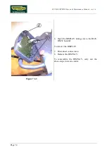
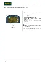
Figure 7.3-1
Carry out the procedures described in paragraph
7.1. “Disassembling the display”.
With the display placed on a work bench:
1. Disconnect keyboard connector
a
.
2. Remove the 5 screws
b
, using a small
Phillips screwdriver.
3. Disconnect the cardio receiver if it is still
connected.
4. Remove the CPU board.
These procedures must be carried out on
a work bench.
To reassemble the CPU BOARD, carry out the
above steps in reverse order
Summary of Contents for RUN 600 XTPRO
Page 1: ...SERVICE MAINTENANCE MANUAL REV 1 3...
Page 2: ......
Page 4: ......
Page 24: ...RUN 600 XTPRO Service Maintenance Manual rev 1 3 Page 2 14 Page intentionally left blank...
Page 36: ...RUN 600 XTPRO Service Maintenance Manual rev 1 3 Page 3 12 Page intentionally left blank...
Page 38: ...RUN 600 XTPRO Service Maintenance Manual rev 1 3 Page 4 2 Page intentionally left blank...
Page 82: ...RUN 600 XTPRO Service Maintenance Manual rev 1 3 Page 6 42 Page intentionally left blank...
Page 126: ...RUN 600 XTPRO Service Maintenance Manual rev 1 3 Page 8 10 Page intentionally left blank...
Page 156: ...RUN 600 XTPRO Service Maintenance Manual rev 1 3 Page 11 14 Page intentionally left blank...
Page 157: ......


