background image

14

Wiring

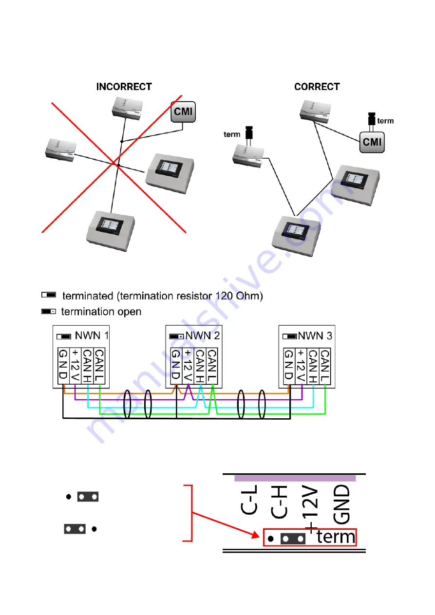
A CAN BUS network should never have a 

star topology

. Rather, the correct topology is a line from the

first device (with terminator) to the second, third and so forth. The last bus device has the termina

-

tion jumper again.

Example

: Connection of three network nodes (NWN) with a 2x2-pole cable and 

termination

 of the ter

-

minal network nodes (network inside one building)

Each CAN network is to be provided with a 120 ohm BUS terminator at the first and last network sub

-

scriber (= 

termination

). This is achieved with a plug-in jumper 

at the back of the controller

. Each CAN

network therefore always has two terminators (one at each end). Branch cables or a star topology

are not permissible for CAN wiring.

Jumper righthand side = 

terminated

Jumper lefthand side = 

not terminated

Summary of Contents for UVR610K

Page 1: ...www ta co at UVR610K FREELY PROGRAMMABLE UNIVERSAL CONTROLLER Console variant Installation instructions English Manual Version 1 17...

Page 2: ...s 9 CAN Bus network 10 Terminal diagram CAN bus cable 10 Guidelines for the topology of a CAN network 10 Technical principles 10 Lightning protection 11 Examples of different network versions 11 Cable...

Page 3: ...this is the case disable the controller and equipment and secure against unintentional use Maintenance If treated and used correctly the device will not require any maintenance Use a cloth mois tened...

Page 4: ...pacing 5 08 mm SD card If an SD card is required this must be a Micro SD card with no more than 32 GB storage capacity and FAT32 formatting Opening the module The device may only be opened at the manu...

Page 5: ...d during the heating season The supplied cable fitting acts as strain relief Installation below the associated coil or heat exchanger is not permissible under any cir cumstances Buffer sensor The sens...

Page 6: ...dance with the relevant local regula tions Note In line with regulations the system must be equipped with protection against lightning surge arrester Sensor failures due to thunderstorms and static el...

Page 7: ...f analogue output A9 to an M Bus interface In the po sition shown at the top the analogue output is active Mains connection Power is supplied through a power supply unit integrated into the module The...

Page 8: ...T500 sensors must be screened If screened cables are used the screen must be connected to the sensor earth GND All sensor leads with a cross section of 0 5 mm2 can be extended to up to 50 metres With...

Page 9: ...when capturing data from two controllers with a single datalogger Never run the data cable together with a CAN BUS cable in the same conduit Terminal diagram DL bus data cable Bus load of DL sensors A...

Page 10: ...ing The BUS cable screen must be connected well at every node to provide continuity For larger net works we recommend including the screen in the equipotential bonding in line with the exam ples shown...

Page 11: ...e 230 V mains supply cable indirect lightning strike appropriate lightning conductors and surge arresters compliant with local regulations must be fitted in the upstream distribution systems In order...

Page 12: ...isconnected network is connected at each bus converter to CAN bus earth GND This screen must not be directly earthed Without CAN Bus surge arresters this version only protects against potential differ...

Page 13: ...n order to be able to communicate with each other Recommendations A 2x2 pole screened twisted pair twist CAN L with CAN H or 12 V with GND with a cable cross section of at least 0 5 mm and a conductor...

Page 14: ...pole cable and termination of the ter minal network nodes network inside one building Each CAN network is to be provided with a 120 ohm BUS terminator at the first and last network sub scriber termin...

Page 15: ...s perfectly with a low number of CAN nodes and an inexpensive J Y St Y EIB KNX 2x2x0 8 KNX bus cable with a char acteristic impedance of 75 to 90 ohm 3 Up to a bus length of 150 m and with only a few...

Page 16: ...e back With jumper J plugged in output 6 is not po tential free Example Connecting a pump C L Phase conductor A6 Normally open contact N O NC Normally closed contact N C If the jumper is unplugged out...

Page 17: ...come the positive pole the GND connection is the negative pole If programmed as a switching output a maximum of 1 HIREL 230V or HIREL PF auxiliary relay can be connected M Bus Output 9 can be converte...

Page 18: ...rminal W therefore corresponds to phase conductor L If the fuse is removed both outputs will be potential free whilst remaining connected to one another via root W The relay module can be connected to...

Page 19: ...or up to 4 M Bus meters 24V Supply for external 24 V devices max 6 W in total including the 12 V devices Max bus load DL bus 100 CAN bus Standard data rate 50 kbit s adjustable from 5 to 500 kbit s Di...

Page 20: ...c from short circuits and from voltage surges in connec tion with the integrated surge protection The glass tube fuse is located on the back of the module Realistic temperatures but faulty operation o...

Page 21: ...relay outputs may also be potential free It is thus only possible to directly switch a 230 V consumer when the appropriate wiring has been implemented If it is not possible to switch the output ON or...

Page 22: ...circuits between cables leads Check for short circuits across GND or screen and the signal cables Check for earth loops for this the screen is undone at each node and the current tested If there is a...

Page 23: ...kaging manual and type label Issuer Technische Alternative RT GmbH A 3872 Amaliendorf Langestra e 124 This declaration is submitted by Dipl Ing Andreas Schneider General manager 19 06 2019 This declar...

Page 24: ...installation instructions or incorrect maintenance 4 The warranty claim will expire if repairs or actions are carried out by persons who are not authorised to do so or have not been so authorised by...

Reviews: