TechniSat SkyFunk 4, Operating Manual
The TechniSat SkyFunk 4 comes with an easy-to-understand Operating Manual that guides you through the product's functionalities. You can conveniently download this comprehensive manual for free from manualshive.com, ensuring a seamless user experience. Explore your device's features and maximize its potential with this downloadable operating manual.
Share
Download


Reviews:
No comments
Related manuals for SkyFunk 4

DTM Series
Brand: W Audio Pages: 12

RSM-1
Brand: Nady Systems Pages: 2

UR-260D
Brand: RELACART Pages: 11

Audita II
Brand: Simeon Pages: 63

SET 7700
Brand: Karma Pages: 20

SmartMyk
Brand: mymyk Pages: 4

LCT 240
Brand: Lewitt Pages: 15

WIreless Microphone and Controller
Brand: SEON Pages: 3

Dummy Head KU 100
Brand: Neumann.Berlin Pages: 20

MH-8800G
Brand: JTS Pages: 18

MINT 220
Brand: DS Pages: 7

SILENT KHIGHT SK-FFT
Brand: Honeywell Pages: 58

CA-UXG1
Brand: JVC Pages: 51

CA-D301T
Brand: JVC Pages: 37
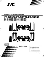
CA-FSSD550
Brand: JVC Pages: 27

CA-UXG110
Brand: JVC Pages: 24

CA-UXF2B
Brand: JVC Pages: 2

CA-UXF70MD
Brand: JVC Pages: 72


