background image

Supplement Airplane Maintenance Manual

Cessna 172 with TAE 125-02-99 / -114

AMM-20-02

Rev. No:
Rev. Date:

Chapter:
Issue:
Issue Date:
Page:
Content:

20-AMM-31-02
3
06.11.2013
3
8

1
25.08.2014

31.60

INDICATING INSTRUMENTS

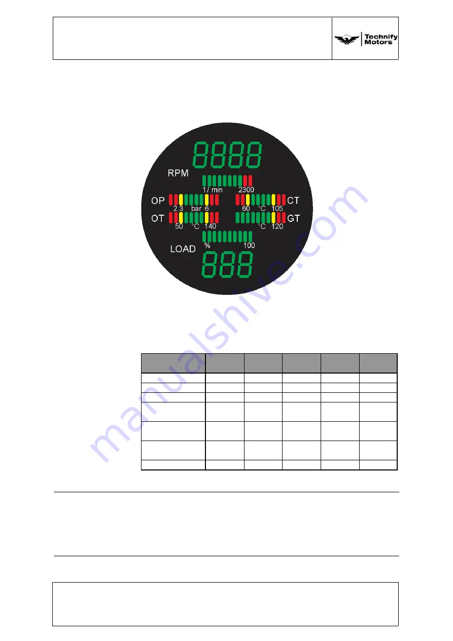
CED 125

Figure 2 CED 125

The engine data of the engine installation to be monitored are
integrated in the combined engine instrument CED-125. 
The ranges of the individual engine monitoring parameters are
shown in the following table. 

Table 31-3a Markings of the CED 125

Instrument

Red 

Range

Amber 

Range

Green 

Range

Amber 

Range

Red 

Range

Tachometer [rpm]

-

-

0-2300

-

> 2300

Oil Pressure [mbar]

0-1200

1200-2300 2300-5200 5200-6000

> 6000

Oil Pressure [psi]

0-17.4

17.4-33.4

33.4-75.4

75.4-87

> 87

Coolant 
Temperature [°C]

< -32

-32...+60

60-101

101-105

> 105

Oil Temperature 
[°C]

< -32

-32...+50

50-125

125-140

> 140

Gearbox 
Temperature [°C]

-

-

< 115

115-120

> 120

Load [%]

-

-

0-100

-

-

Note:

If an engine reading is in the amber or red range, the "Caution"
lamp is activated. It only extinguishes when the
"CED/AED-Test/Confirm" button is pressed. If this test button is
pressed longer than a second, a self test of the instrument is
initiated.

Summary of Contents for Cessna 172

Page 1: ... safety information Note The Supplement to the Airplane Maintenance Manual is to be included with every Cessna 172 TAE 125 02 99 and TAE 125 02 114 installation Note Please report any service difficulties to the Technical Support Center at Technify Motors GmbH See above for contact information CAUTION The organizations and staff who carry out these maintenance action must be approved by the author...

Page 2: ...roperty of Technify Motors GmbH and may not be reproduced either in full or in part or passed on to a third party without written consent from Technify Motors GmbH This text must be included in any full or partial reproduction of this documentation Copyright Technify Motors GmbH ...

Page 3: ...AL 4 01 4 VALIDITY OF THIS MANUAL 5 01 5 ABBREVIATIONS 5 01 6 PACKING AND TRANSPORT 5 01 7 STORAGE 5 01 8 QUALIFICATIONS OF THE OPERATING AND MAIN TENANCE PERSONNEL 5 01 9 UPDATE INFORMATION SERVICE 5 01 10 SERVICE LIFE OF THE ENGINE 6 01 11 CONVERSION FACTORS 7 04 AIRWORTHINESS LIMITATIONS ISSUE 3 1 04 1 ENGINE LIFE LIMIT 1 04 2 MANDATORY MAINTENANCE ACTIONS 1 04 3 LOG OF REVISIONS TO AIRWORTHINE...

Page 4: ...lacards and Markings 1 11 10 Interior Placards 2 12 SERVICING 1 12 00 GENERAL 1 12 10 REPLENISHING 4 12 20 SCHEDULED SERVICING 7 20 STANDARD PRACTICES AIRFRAME 1 20 00 GENERAL 1 20 10 Standard Torque Values 1 20 20 Firewall Sealants 3 21 ENVIRONMENTAL SYSTEMS 1 21 00 GENERAL 1 24 ELECTRICAL POWER 1 24 00 GENERAL 1 24 30 DC GENERATION 2 24 50 ELECTRICAL LOAD DISTRIBUTION 9 28 FUEL 1 28 00 GENERAL 1...

Page 5: ...60 INDICATING INSTRUMENTS 3 31 70 Sensors 6 37 VACUUM 1 37 00 GENERAL 1 61 PROPELLER 1 61 10 CONSTANT SPEED PROPELLER 1 61 20 CONSTANT SPEED UNIT 1 71 POWER PLANT 1 71 00 GENERAL 1 71 20 MOUNTS 30 71 40 ATTACH FITTINGS 32 71 60 AIR INTAKES 41 73 ENGINE FUEL SYSTEM 1 73 00 GENERAL 1 74 IGNITION 1 74 00 GENERAL 1 75 LIQUID COOLING 1 75 00 GENERAL 1 77 ENGINE INDICATION 1 77 00 GENERAL 1 78 EXHAUST 1...

Page 6: ... 99 114 AMM 20 02 Chapter Issue Issue Date Page Content 20 AMM 01 02 3 06 11 2013 4 4 Rev No Rev Date 1 25 08 2014 79 OIL 1 79 00 GENERAL 1 79 30 INDICATING 5 80 STARTING 1 80 00 GENERAL 1 91 CHARTS AND WIRING DIAGRAMS 1 91 10 WIRING DIAGRAMS 1 91 20 SPECIAL TOOLS 39 ...

Page 7: ... 3 0 25 08 2014 Heinich 20 AMM 12 02 3 1 25 08 2014 Heinich 20 AMM 20 02 3 1 25 08 2014 Heinich 20 AMM 21 02 3 1 25 08 2014 Heinich 20 AMM 24 02 3 1 25 08 2014 Heinich 20 AMM 28 02 3 1 25 08 2014 Heinich 20 AMM 31 02 3 1 25 08 2014 Heinich 20 AMM 37 02 3 1 25 08 2014 Heinich 20 AMM 61 02 3 1 25 08 2014 Heinich 20 AMM 71 02 3 1 25 08 2014 Heinich 20 AMM 73 02 3 1 25 08 2014 Heinich 20 AMM 74 02 3 1...

Page 8: ......

Page 9: ...ce must also be taken into account Please contact Technify Motors GmbH if you have any questions We would be glad to assist you further 01 1 ACCOMPANYING APPLICABLE DOCUMENTS Aircraft manufacturer s Service Manual Aircraft manufacturer s Airplane Maintenance Manual Engine Installation Manual IM 02 02 Kit Installation Manual IM 20 02 Repair Manual RM 02 02 Operation and Maintenance Manual OM 02 02 ...

Page 10: ...20 AMM 01 02 3 06 11 2013 2 8 Rev No Rev Date 1 25 08 2014 01 2 IDENTIFICATION OF Components Engine identification The serial number of the engine is provided on the type plate on the crankcase near the starter flange Example Figure 1 Type Plate Note When making inquiries always have the serial number of the engine ready ...

Page 11: ...by a part number and a serial number as shown in the following picture The first part constitutes the part number the last four digits are the serial number Figure 2 Identification of Engine Mount AED CED identification The AED and CED are indicated by a label as shown below As an example the identification label of an AED is shown the layout of the CED label is similar Figure 3 Identification Lab...

Page 12: ...gns are used in the manual They must be heeded strictly to prevent injury and material damage to avoid impairment of the operating safety of the aircraft and to rule out any damage to the aircraft as a consequence of improper handling The indications right left front and rear are always relative to the flight direction The following symbol is used Example of flight direction right WARNING Disregar...

Page 13: ...According to the Operation and Maintenance Manual OM 02 02 01 7 STORAGE According to the Operation and Maintenance Manual OM 02 02 01 8 QUALIFICATIONS OF THE OPERATING AND MAINTENANCE PERSONNEL Tasks described in this manual may be performed only by trained personnel having necessary certificates and licenses All locally applicable national and international regulations must be observed 01 9 UPDAT...

Page 14: ... Manual Cessna 172 with TAE 125 02 99 114 AMM 20 02 Chapter Issue Issue Date Page Content 20 AMM 01 02 3 06 11 2013 6 8 Rev No Rev Date 1 25 08 2014 01 10 SERVICE LIFE OF THE ENGINE For Service Life of the engine refer to Chapter 04 ...

Page 15: ... 4 mm Foot ft ft x 0 3048 m Nautical mile nm nm x 1 852 km Statute mile sm sm x 1 609 km LENGTH Unit Abbreviation Conversion Factor Conversion Factor SI to US Imperial US Imperial to SI Kilometers per hour km h km h 1 852 kts km h 1 609 mph Meters per second m s m s 196 85 fpm Miles per hour mph mph x 1 609 km h Knots kts kts x 1 852 km h Feet per minute fpm fpm 196 85 m s SPEED Unit Abbreviation ...

Page 16: ...nit Abbreviation Conversion Factor Conversion Factor SI to US Imperial US Imperial to SI Liter l l 3 7854 US gal l 0 9464 US qt l 4 5459 Imp gal l 61 024 in 3 US gallon US gal US gal x 3 7854 l US quart US qt US qt x 0 9464 l Imperial gallon Imp gal Imp gal x 4 5459 l Cubic inch in 3 in 3 x 61 024 l VOLUME Unit Abbreviation Conversion Factor Conversion Factor SI to US Imperial US Imperial to SI Ne...

Page 17: ...to service bulletin TM TAE 125 0001 This limit calls for replacement of the entire engine No overhauls are allowed to the core engine No repairs outside the published ICA s allowed to the engine 04 2 MANDATORY MAINTENANCE ACTIONS Mandatory maintenance actions of the engine are listed in Chapter 02 OM 05 02 of the current Operation and Maintenance Manual OM 02 02 AIRWORTHINESS LIMITATIONS AIRWORTHI...

Page 18: ...na 172 with TAE 125 02 99 114 AMM 20 02 Chapter Issue Issue Date Page Content 20 AMM 04 02 3 06 11 2013 2 2 Rev No Rev Date 1 25 08 2014 04 3 LOG OF REVISIONS TO AIRWORTHINESS LIMITATIONS AIRWORTHINESS LIMITATIONS Rev No Description of Revision ...

Page 19: ...rer s specifications refer to airplane manual WARNING The entire engine has a service life time between replacement refer to Chapter 04 of this manual WARNING It is strongly recommended that the maintenance intervals specified by the manufacturer should be adhered to Non compliance with the maintenance schedule can amongst other things lead to lapse of any claims to warranty Note For this engine a...

Page 20: ...ust be checked 05 20 SCHEDULED MAINTENANCE CHECKS A PROPELLER GROUP Refer to Operation and Installation Manual of MT Propeller E124 ATA 61 01 24 for Inspections and Maintenance of the propeller MTV 6 A 187 129 B ENGINE GROUP Note If propeller nuts need to be replaced nuts NM 0000 00268 01 can be used alternatively when installing the propeller WARNING Under extreme conditions such as low usage com...

Page 21: ...ct for cracks Check turbocharger hoses for damages chafe marks cracks etc especially damaged fabric Visual inspection of the joints e g hose connections Replace fuel filter refer to Chapter 28 Section 28 20 Maintenance Practices Check airplane fuel pump Cessna R S only refer to airplane manufacturer s specifications Check electrical fuel pump refer to manufacturer s specifications Further maintena...

Page 22: ...ntenance Manual OM 02 02 Every 1200 operating hours Work as described for every 200 operating hours Work as described for every 300 operating hours Replace the turbocharger clamp refer to Chapter 71 Section 71 60 Maintenance Practices TAE 125 02 114 only Further maintenance action according to Operation and Maintenance Manual OM 02 02 Every 1500 operating hours TAE 125 02 99 Work as described for ...

Page 23: ...0 Maintenance Practices Visual inspection and function test of all 14V 28V converters if installed refer to Chapter 24 Section 24 50 Maintenance Practices Further maintenance action according to Operation and Maintenance Manual OM 02 02 Every 60 months Check engine mount for signs of corrosion refer to Chapter 71 Section 71 20 Maintenance Practices Inspect the radiator mounts refer to Chapter 71 S...

Page 24: ... switch Alternator relay Battery fuse Alternator fuse if installed 50A FADEC fuse 100A Main Bus fuse FADEC IGN switch C Airframe Group 5 20 03 Checks dependent on engine operating time Every 100 operating hours annual inspection Inspect cowling openings oil inspection cover air ducts for damage Inspect all supports for main battery FADEC Backup battery excitation batteries etc Check Load Selector ...

Page 25: ...den stoppage loss of oil over temperature lightning strike propeller strike Refer to Operation and Maintenance Manual OM 02 02 Repair Manual RM 02 02 Engine Manufacturer Technify Motors GmbH for necessary corrective actions and repair Note Repairs which are not described in this manual may only be carried out in accordance with a repair scheme which has been approved by the manufacturer or the com...

Page 26: ...ment Airplane Maintenance Manual Cessna 172 with TAE 125 02 99 114 AMM 20 02 Chapter Issue Issue Date Page Content 20 AMM 05 02 3 06 11 2013 8 8 Rev No Rev Date 1 25 08 2014 This page intentionally left blank ...

Page 27: ... 135 hp 99 kw TAE 125 02 99 155 hp 114 kw TAE 125 02 114 Rated Speed 2300 rpm Fuels approved JET A 1 JET A JP 8 JP 8 100 Jet Fuel No 3 GB 6537 2006 Diesel DIN EN 590 TS 1 GOST 10227 86 TS 1 GSTU 320 00149943 011 99 SASOL GTL Diesel Engine Oil AeroShell Oil Diesel Ultra AeroShell Oil Diesel 10W 40 Shell Helix Ultra 5W 30 Shell Helix Ultra 5W 40 Engine Oil Sump Capacity 4 5 to 6 0 liters 1 19 to 1 5...

Page 28: ...pacity Gearbox 1 liter 0 26 US gal Coolant Water Radiator Protection at a ratio of 50 50 Radiator Protection BASF Glysantin Protect Plus G48 Mobil Antifreeze Extra G48 ESSO Antifreeze Extra G48 Comma Xstream Green Concen trate G48 Valvoline Zerex Glysantin G 48 Gear Reduction 1 689 1 06 3 PROPELLER Manufacturer MT Propeller Entwicklung GmbH Flugplatzstrasse 1 D 94348 Atting Model MTV 6 A187 129 Nu...

Page 29: ...S gal 120 0 l total unusable fuel 4 0 US gal 15 1 l 2 Long range tanks each 22 1 US gal 83 65 l total capacity 44 2 US gal 167 3 l total usable fuel 40 2 US gal 152 2 l total unusable fuel 4 0 US gal 15 1 l C 172 N P 2 Standard tanks each 18 3 US gal 69 4 l total capacity 36 6 US gal 138 8 l total usable fuel 33 6 US gal 127 4 l total unusable fuel 3 0 US gal 11 4 l 2 Long range tanks each 22 95 U...

Page 30: ...l total capacity 47 9 US gal 181 4 l total usable fuel 41 9 US gal 158 6 l total unusable fuel 6 US gal 22 8 l C 172 R S normal category 2 tanks each 23 8 US gal 90 1 l total capacity 47 6 US gal 180 2 l total usable fuel 44 6 US gal 168 8 l total unusable fuel 3 0 US gal 11 4 l C 172 R S utility category 2 tanks each 15 5 US gal 58 7 l total capacity 31 0 US gal 117 4 l total usable fuel 28 0 US ...

Page 31: ...bes all additional decals provided when installing a TAE 125 02 99 114 engine 11 00 Exterior Placards and Markings Placards General Fuel Capacity Decals are attached to both tanks Figure 11 1 Cessna F G H Figure 11 2 Cessna F M long range Figure 11 3 Cessna I K L M Figure 11 4 Cessna N P long range Note Refer to the original Aircraft Maintenance Manual for information on type removal and installat...

Page 32: ...ate Page Content 20 AMM 11 02 3 25 08 2014 2 4 Rev No Rev Date Figure 11 5 Cessna N P Figure 11 6 Cessna P integral Figure 11 7 Cessna R S Figure 11 8 Cessna R S utility 11 10 Interior Placards Placards General Engine Oil The decal is attached to the inside of the oil dipstick inspection door Figure 11 9 ...

Page 33: ...T BOTH 114 4 ltr 57 2 ltr 57 2 ltr STANDARD TANKS 40 2 gal 20 1 gal 20 1 gal LEFT RIGHT BOTH 152 2 ltr 76 1 ltr 76 1 ltr LONG RANGE TANKS 31 7 gal 15 85 gal 15 85 gal 120 ltr 60 ltr 60 ltr C172 I K L M 33 6 gal 16 8 gal 16 8 gal 127 4 ltr 63 7 ltr 63 7 ltr C172 N P 41 9 gal 20 9 gal 20 9 gal 158 6 ltr 79 3 ltr 79 3 ltr 44 6 gal 22 3 gal 22 3 gal 168 8 ltr 84 4 ltr 84 4 ltr C172 R S 98 4 ltr 26 gal...

Page 34: ...Supplement Airplane Maintenance Manual Cessna 172 with TAE 125 02 99 114 AMM 20 02 Chapter Issue Issue Date Page Content 20 AMM 11 02 3 25 08 2014 4 4 Rev No Rev Date This page intentionally left blank ...

Page 35: ... Chapter Issue Issue Date Page Content 20 AMM 12 02 3 06 11 2013 1 8 1 25 08 2014 12 SERVICING 12 00 GENERAL The following figures show the service points of the engine installation Figure 1 Service Point TAE 125 02 99 1 Engine Oil Filter Figure 2 Service Points TAE 125 02 114 1 Engine Oil Filter 1 ...

Page 36: ...ue Issue Date Page Content 20 AMM 12 02 3 06 11 2013 2 8 Rev No Rev Date 1 25 08 2014 Figure 3 Service Points TAE 125 02 99 2 Micro Filter Single Stage Pump 3 Gearbox Oil Inspection Glas Figure 4 Service Points TAE 125 02 114 2 Micro Filter Single Stage Pump 3 Gearbox Oil Inspection Glas 2 3 2 3 ...

Page 37: ...re must be taken when cleaning the engine compartment If leaks are noticed determine their location before cleaning The engine has to be cold before cleaning The use of cold cleansers is recommended for instance Berner Kaltreiniger Art no 13618 0 Do not clean the engine electrical system because it could be damaged Do not use high pressure cleaning equipment Dry the engine after cleaning with pres...

Page 38: ...r samples until the fuel is clear and then gently rock the wings and lower tail to the ground to move any additional contaminants to the sampling points Take repeated samples from all fuel drain points until all contamination has been removed If contaminants are still present refer to following WARNING and do not fly the airplane WARNING Observe all required safety precautions for handling kerosen...

Page 39: ...nd the drain valve in the header tank to defuel the airplane Engine Oil System Check engine oil level before each flight according to the appropriate POH supplement Change engine oil and engine oil filter according to Operation and Maintenance Manual OM 02 02 Gearbox Oil System Check gearbox oil level before each flight according to the appropriate POH supplement Change gearbox oil and gearbox oil...

Page 40: ...ose and allow the coolant to drain into a prepared collecting container 5 Open the cover of the coolant filler this allows the coolant to drain faster 6 After draining tighten the drain plug Tightening torque 10 Nm 7 4 lbf ft 7 Reconnect the lower hoses of the water radiator and the heat exchanger and tighten the clamps B Fill up new coolant 1 Fill up the cooling system with coolant according to C...

Page 41: ...on and Installation Manual of MT Propeller E124 ATA 61 01 24 for Inspections and Maintenance of the propeller MTV 6 A 187 129 Power Plant Regularly check the engine compartment for oil and fuel leaks chafing of lines loose wires and tightness of all parts Be careful when cleaning the engine compartment Refer to Chapter 12 00 of this Chapter Induction Air Filter Regularly check and change the Induc...

Page 42: ...ment Airplane Maintenance Manual Cessna 172 with TAE 125 02 99 114 AMM 20 02 Chapter Issue Issue Date Page Content 20 AMM 12 02 3 06 11 2013 8 8 Rev No Rev Date 1 25 08 2014 This page intentionally left blank ...

Page 43: ...e tables below Always use the correct locking device with the nut or bolt These tables show the correct torque values for bolts and nuts to AN and DIN specifications Use the following torque values for all bolts nuts and screws which meet the specifications unless they are in the list of special torque values below Table 1 Tightening torques for set screws in accordance with VDI standard 2230 CAUT...

Page 44: ...ectors Special Torque Values Table 3 Special torque values Dash Size Material Nm Dash 03 Aluminium 10 Stahl 14 Dash 04 Aluminium 15 Stahl 20 Dash 06 Aluminium 20 Stahl 30 Dash 08 Aluminium 35 Stahl 55 Dash 10 Aluminium 45 Stahl 75 Dash 12 Aluminium 55 Stahl 105 Part Nm Propeller to engine bolts Refer to MT Propeller OPERATION AND INSTALLATION MANUAL ATA 61 01 24 E 124 Bolts attaching the engine mo...

Page 45: ...C DeSoto International Hutchinson PR 812 Hutchinson Le Joint Français 84 116 rue Salvador Allende B P 16F 95870 Bezons France or PRC DeSoto International Inc 5454 San Fernando Road PO Box 1800 Glendale California 91209 PRC DeSoto International PS 700 PRC DeSoto International Inc 5454 San Fernando Road PO Box 1800 Glendale California 91209 Flamemaster CS 1900 Flamemaster Corporation Supercedes 1112...

Page 46: ...ment Airplane Maintenance Manual Cessna 172 with TAE 125 02 99 114 AMM 20 02 Chapter Issue Issue Date Page Content 20 AMM 20 02 3 06 11 2013 4 4 Rev No Rev Date 1 25 08 2014 This page intentionally left blank ...

Page 47: ...oil The heat exchanger for cabin heat is installed inline with the unregulated exit of the cooling system thermostat Engine coolant passes through the heater core and heats incoming air The coolant flow through the heater core is always open The warm air supply is regulated by the pilot over the heating valve In normal operation the control knob Shut off Cabin Heat must be open with the control kn...

Page 48: ... TAE 125 02 99 114 AMM 20 02 Chapter Issue Issue Date Page Content 20 AMM 21 02 3 06 11 2013 2 6 Rev No Rev Date 1 25 08 2014 Figure 2 Coolant System TAE 125 02 114 Figure 3 Heat Exchanger TAE 125 02 99 114 1 Heat Exchanger 2 Coolant OUT 3 Coolant IN 1 2 3 ...

Page 49: ... Issue Date Page Content 20 AMM 21 02 3 06 11 2013 3 6 1 25 08 2014 Figure 4 Coolant Hose System TAE 125 02 99 1 Coolant Hose Heat Exchanger IN 2 Coolant Hose Heat Exchanger OUT Figure 5 Coolant Hose System TAE 125 02 114 1 Heat Exchanger 2 Coolant Hose Heat Exchanger OUT 3 Coolant Hose Heat Exchanger IN 1 2 1 2 ...

Page 50: ...apter Issue Issue Date Page Content 20 AMM 21 02 3 06 11 2013 4 6 Rev No Rev Date 1 25 08 2014 Figure 6 Air Hose System C 172 F G H I K L M N P TAE 125 02 99 1 Air Hose Heat Exchanger to Firewall Figure 7 Air Hose System C 172 R S TAE 125 02 99 1 Air Hose Heat Exchanger to Firewall 1 1 ...

Page 51: ... 99 114 AMM 20 02 Rev No Rev Date Chapter Issue Issue Date Page Content 20 AMM 21 02 3 06 11 2013 5 6 1 25 08 2014 Figure 8 Air Hose System for all versions with TAE 125 02 114 installation Figure 9 Air Hose assembled for all versions with TAE 125 02 114 installation ...

Page 52: ...ment Airplane Maintenance Manual Cessna 172 with TAE 125 02 99 114 AMM 20 02 Chapter Issue Issue Date Page Content 20 AMM 21 02 3 06 11 2013 6 6 Rev No Rev Date 1 25 08 2014 This page intentionally left blank ...

Page 53: ...ls to produce current accompanied by a zero indication on the AED 125 The battery switch BAT must be ON before any electrical equipment will operate In addition to the main battery and alternator a backup battery which only supplies power to FADEC A is part of the electrical system when installed The FADEC backup battery is integrated into the electrical system without manual control The pilot can...

Page 54: ...only alternator without internal regulator 28V version only regulator 28V version only excitation battery ammeter or accessories will cause severe damage to units and or wiring CAUTION Disconnect main battery before connecting or disconnecting the excitation or backup battery The excitation battery wire from the alternator 14V version or from the regulator 28V version may carry electrical power ev...

Page 55: ... alternator Trouble Check Corrective Action Check alternator wiring Replace alternator wiring Check alternator fuse Replace alternator fuse Check alternator relay Replace alternator relay Check alternator switch Replace alternator switch Check alternator funcion Replace alternator Check excitation battery Replace excitation battery Check excitation battery wiring Repair wiring FADEC backup battery...

Page 56: ... to the battery manufacturer s specifications refer to 01 1 Check for incorrect mounting Check the terminal connections 4 Disconnecting Connecting the Main Battery for Maintenance A Disconnect the Main Battery for Maintenance 1 Remove the bottom of the extended baggage area Refer to the airplane manufacturers specifications 2 Remove the cover from the battery box 3 Disconnect the negative cable fr...

Page 57: ...rom the main battery D Connect the Main Battery after Maintenance 1 Connect the positive cable to the main battery 2 Connect the negative cable to the main battery 3 Install the cover to the battery box 4 Install the bottom of the extended baggage area Refer to the airplane manufacturer s specifications CAUTION Make sure that you connect the cables to the correct terminals Incorrect connection can...

Page 58: ...e 1 Make sure that the main battery is dry and clean 2 Place the main battery into position in the battery box 3 Connect the positive cable to the main battery 4 Connect the negative cable to the main battery 5 Install the cover to the battery box 6 Install the bottom of the extended baggage area Refer to the airplane manufacturer s specifications 6 Charging the Main Battery 1 Engine Master off 2 ...

Page 59: ...e cable from the excitation battery 4 Remove the battery carrier top 5 Remove the excitation battery from the airplane B Install the new Excitation Battery 1 Place the excitation battery into position in the battery carrier bottom 2 Install the battery carrier top 3 Connect the positive cable to the excitation battery 4 Connect the negative cable to the excitation battery 5 Connect the main batter...

Page 60: ...e 2 Disconnect the negative cable from the backup battery 3 For 28V system only disconnect the cable which interconnects the two batteries 4 Disconnect the positive cable from the backup battery 5 Remove the battery carrier top 6 Remove the backup battery from the airplane B Install the new Backup Battery 1 Place the backup battery into position in the battery carrier bottom 2 Install the battery ...

Page 61: ...l 14V 28V converters if installed 2 Inspecting the relays This is a visual inspection Inspect whether the connections of the relays are firmly attached In addition the relays have to be checked for signs of corrosion Depending on installation inspect the following relays Battery Relay located in the Junction Box on the firewall Alternator Relay located in the Junction Box on the firewall Glow Rela...

Page 62: ...C172 F G H I K L M N P located on the LH of the airframe underneath the Panel LH A Accomplish the function test of the Battery Relay 1 Battery Switch ON 2 AED CED illuminate without data 3 Fuel Pump functional switch Fuel Pump 4 Battery Relay OK 5 Battery Switch OFF B Accomplish the function test of the Alternator Relay 1 Battery Switch ON 2 Alternator Switch ON or c b Alternator push in 3 A voltm...

Page 63: ... ON 2 Main Bus Switch ON 3 Avionics Lights etc functional 4 Main Bus Relay OK 5 Main Bus Switch OFF 6 Battery Switch OFF 5 Accomplishing a function test of all switches knobs Depending on installation test the following switches Main Bus Switch Engine Master Switch Force B Switch FADEC Test Knob AED CED Test Knob Alternator A Inspect all switches knobs 1 Visual inspect all switches knobs on signs ...

Page 64: ...h OFF 6 Battery Switch OFF C Accomplish the function test of the Engine Master Switch 1 Battery Switch ON 2 Engine Master ON AED CED indicate data 3 Start engine 4 Load Selector IDLE 5 Accomplish FADEC Test procedure OK 6 Battery Switch OFF Engine must run without Battery 7 Switch FADEC A to FADEC B using the Force B switch Engine running OK 8 Engine Master Switch OK 9 Engine Master OFF 10 Battery...

Page 65: ...tch OK 7 Engine Master OFF 8 Battery Switch OFF E Accomplish the function test of the FADEC Test Knob 1 Battery Switch ON 2 Engine Master ON 3 Start engine 4 Load Selector IDLE 5 Push FADEC test knob Test procedure OK 6 FADEC Test knob OK 7 Engine Master OFF 8 Battery Switch OFF WARNING Only run the engine on the ground with the propeller running even for testing purposes in a safe and clear area ...

Page 66: ...on Load current AED Voltage 14V AED Alternator Warning Lamp AWL off 6 Alternator off No load current voltage 14V Alternator Warning Lamp on 7 Alternator OK 8 Engine Master OFF 9 Battery Switch OFF 6 Accomplishing a function test of all Circuit Breakers The following circuit breakers must be tested FADEC A B AED CED Starter A Accomplish the function test of the Circuit Breaker FADEC A B 1 Battery S...

Page 67: ...D OK 5 Engine Master OFF 6 Battery Switch OFF C Accomplish the function test of the Circuit Breaker Starter 1 Battery Switch ON 2 Engine Master ON 3 Switch Starter via Circuit Breaker Starter 4 Circuit Breaker Starter OK 5 Engine Master OFF 6 Battery Switch OFF 7 Accomplishing a function test of all 14V 28V converters if installed A Accomplish the function test of all 14V 28V converters 1 Battery ...

Page 68: ...ent Airplane Maintenance Manual Cessna 172 with TAE 125 02 99 114 AMM 20 02 Chapter Issue Issue Date Page Content 20 AMM 24 02 3 06 11 2013 16 16 Rev No Rev Date 1 25 08 2014 This page intentionally left blank ...

Page 69: ...e fuel is injected into the cylinders depending upon the position of the thrust lever and regulation by the FADEC In TAE 125 02 99 installations surplus fuel flows to the filter module and then through the fuel selector valve back into the pre selected tank A thermostat switch in the filter module controls the heat exchange between the fuel feed and return In TAE 125 02 114 installations surplus f...

Page 70: ...na 172 with TAE 125 02 99 114 AMM 20 02 Chapter Issue Issue Date Page Content 20 AMM 28 02 3 06 11 2013 2 20 Rev No Rev Date 1 25 08 2014 28 20 DISTRIBUTION 1 TAE 125 02 99 installation Figure 1 Fuel System Diagram C 172 F G H I K L M left right ...

Page 71: ...intenance Manual Cessna 172 with TAE 125 02 99 114 AMM 20 02 Rev No Rev Date Chapter Issue Issue Date Page Content 20 AMM 28 02 3 06 11 2013 3 20 1 25 08 2014 Figure 2 Fuel System Diagram C 172 F G H I K L M left right both ...

Page 72: ...plane Maintenance Manual Cessna 172 with TAE 125 02 99 114 AMM 20 02 Chapter Issue Issue Date Page Content 20 AMM 28 02 3 06 11 2013 4 20 Rev No Rev Date 1 25 08 2014 Figure 3 Fuel System Diagram C 172 N P left right ...

Page 73: ...ne Maintenance Manual Cessna 172 with TAE 125 02 99 114 AMM 20 02 Rev No Rev Date Chapter Issue Issue Date Page Content 20 AMM 28 02 3 06 11 2013 5 20 1 25 08 2014 Figure 4 Fuel System Diagram C 172 N P left right both ...

Page 74: ...t Airplane Maintenance Manual Cessna 172 with TAE 125 02 99 114 AMM 20 02 Chapter Issue Issue Date Page Content 20 AMM 28 02 3 06 11 2013 6 20 Rev No Rev Date 1 25 08 2014 Figure 5 Fuel System Diagram C 172 R S ...

Page 75: ...ce Manual Cessna 172 with TAE 125 02 99 114 AMM 20 02 Rev No Rev Date Chapter Issue Issue Date Page Content 20 AMM 28 02 3 06 11 2013 7 20 1 25 08 2014 2 TAE 125 02 114 installation Figure 6 Fuel System Diagram C 172 F G H I K L M ...

Page 76: ...3 8 20 Rev No Rev Date 1 25 08 2014 Figure 7 Fuel System Diagram C 172 N P Fuel tank right Engine Fuel Filter Module Fuel tank left Fuel selector 60 C Fuel tank venting line Fuel tank temperature indication Fuel tank level indication Low fuel warning Electric Pump Shut off valve Reservoir tank Reservoir tank venting line Check valve Fuel cooler ...

Page 77: ...8 02 3 06 11 2013 9 20 1 25 08 2014 Figure 8 Fuel System Diagram C 172 R S Fuel tank right Engine Fuel Filter Module Fuel tank left Fuel selector 60 C Fuel tank venting line Fuel tank temperature indication Fuel tank level indication Low fuel warning Electric Pump Shut off valve Reservoir tank Reservoir tank venting line Check valve Fuel cooler ...

Page 78: ...9 114 AMM 20 02 Chapter Issue Issue Date Page Content 20 AMM 28 02 3 06 11 2013 10 20 Rev No Rev Date 1 25 08 2014 Fuel Filter Bowl Figure 9 Figure 10 Fuel Filter Bowl Disassembled 1 Top Lid 2 Fuel Filter Housing 3 Fuel Filter Cartridge 4 Spring 5 Bottom Lid 1 2 3 4 5 ...

Page 79: ...l Cessna 172 with TAE 125 02 99 114 AMM 20 02 Rev No Rev Date Chapter Issue Issue Date Page Content 20 AMM 28 02 3 06 11 2013 11 20 1 25 08 2014 Figure 11 Bottom Lid with O ring 6 Lid 7 O Ring Figure 12 Bleed screw in top lid 8 Bleed Screw ...

Page 80: ...ect all lines and openings of the housing from contamination B Replace the Fuel Filter Cartridge 1 Unscrew the bottom lid 5 of the filter using a 27mm wrench Remove the fuel filter cartridge 3 from the fuel filter housing See Figure 10 2 Replace the O Ring 6 in the bottom lid 5 set it carefully in the groove Stretching the ring a little helps to retain it in the groove See Figure 11 3 Insert the n...

Page 81: ...he top lid of the fuel filter assembly 2 Bleed the fuel filter bowl by opening the allen head screw opening the fuel selector valve and activating the auxiliary fuel feed pump until fuel drains from the opening Replace and tighten the allen head screw ensuring the crush washer is in place See Figure 12 3 Conduct a ground run after completing any other maintenance on the aircraft 28 40 INDICATING D...

Page 82: ...3 06 11 2013 14 20 Rev No Rev Date 1 25 08 2014 TROUBLESHOOTING Table 28 1a Troubleshooting Low Fuel Sensor Trouble Ca use Corre ctive Action Fuel low level warning lam p illum inate on the lightpanel when the tank has m ore than 2 6 US gal C 172 F G H I K L M N P or 5 US gal C 172 R S Low Fuel Sensor defective Replace Low Fuel Sensor ...

Page 83: ... tank Refer to the aircraft manufacturer s specifications 2 Disconnect the electrical cables for the low fuel sensor 3 Remove the rivets of the fitting for the low fuel sensor 4 Remove the fitting of the low fuel sensor 5 Remove the low fuel sensor out of the fitting See Figure 13 WARNING Avoid contact with fuel Fuel can cause skin disease WARNING Do not allow fire near fuel Fuel burns and causes ...

Page 84: ...the fitting D Install the new Low Fuel Sensor 1 Refer to IM 20 02 3 Replacing the Fuel Temperature Sensor C 172 F G H I K L M N P A Remove the Fuel Temperature Sensor 1 Remove the tank Refer to the aircraft manufacturer s specifications 2 Remove the rivets of the fitting for the fuel temperature sensor 3 Remove the fitting of the fuel temperature sensor 4 Remove the cover of the fitting 5 Disconne...

Page 85: ...hapter Issue Issue Date Page Content 20 AMM 28 02 3 06 11 2013 17 20 1 25 08 2014 Figure 14 Fuel Temperature Sensor C 172 F G H I K L M N P 1 Cover 2 Fuel Temperature Sensor 3 Seal Ring 4 Connector 5 Fitting 7 Clean the tank and the fitting F Install the new Fuel Temperature Sensor 1 Refer to IM 20 02 ...

Page 86: ...014 4 Replacing the Fuel Temperature Sensor C 172 R S A Remove the Fuel Temperature Sensor 1 Remove the access panel See Figure 15 Figure 15 Access Panel C 172 R S 2 Disconnect the connector of the fuel temperature sensor 3 Remove the fuel temperature sensor See Figure 16 Figure 16 Fuel Temperature Sensor C 172 R S 1 Connector 2 Fuel Temperature Sensor Access Panel Access Panel ...

Page 87: ... 02 99 114 AMM 20 02 Rev No Rev Date Chapter Issue Issue Date Page Content 20 AMM 28 02 3 06 11 2013 19 20 1 25 08 2014 4 Make sure that the tank and the adapter of the fuel temperature sensor are clean C Install the new Fuel Temperature Sensor 1 Refer to IM 20 02 ...

Page 88: ...ent Airplane Maintenance Manual Cessna 172 with TAE 125 02 99 114 AMM 20 02 Chapter Issue Issue Date Page Content 20 AMM 28 02 3 06 11 2013 20 20 Rev No Rev Date 1 25 08 2014 This page intentionally left blank ...

Page 89: ...ich is installed on the instrument panel with the following functions Table 31 1a Description of the Light panel C 172 F G H I K L M N P Figure 1 Light panel C 172 F G H I K L M N P Lightpanel Function FADEC Test Knob A FADEC B Warning lights for FADEC A and B Alt Alternator Warning light AED AED Caution light for AED 125 CED CED Caution light for CED 125 CED AED Test Confirm knob for CED 125 AED ...

Page 90: ...ight panel C 172 R S Figure 1Light panel C 172 R S Lightpanel Function FADEC Test Knob A FADEC B Warning Lights for FADEC A and B Force B Switch for FADEC Alt Alternator Warning light AED AED Caution light for AED 125 CED CED Caution light for CED 125 CED AED Test Confirm knob for CED 125 AED 125 an Caution lights Glow Glow Control light C 172 R S F O R C E B A B F A D E C T e s t C o n f i r m CE...

Page 91: ...e Table 31 3a Markings of the CED 125 Instrument Red Range Amber Range Green Range Amber Range Red Range Tachometer rpm 0 2300 2300 Oil Pressure mbar 0 1200 1200 2300 2300 5200 5200 6000 6000 Oil Pressure psi 0 17 4 17 4 33 4 33 4 75 4 75 4 87 87 Coolant Temperature C 32 32 60 60 101 101 105 105 Oil Temperature C 32 32 50 50 125 125 140 140 Gearbox Temperature C 115 115 120 120 Load 0 100 Note If ...

Page 92: ... Level for low level of coolant Indication of fuel temperature in the fuel tanks Voltage Fuel flow 75 30 75 30 30 22 5 5 FUEL TEMP RIGHT C FUEL TEMP LEFT C V VOLT FUEL FLOW gal h WATER LEVEL 60 A AMPERE Note For Cessna 172 R S installation there is no ammeter on the AED display Note If an airplane reading is in the amber or red range the Caution lamp is activated It only extinguishes when the CED ...

Page 93: ...L signal A Drain the Coolant from the Expansion Tank 1 Remove the cap of the expansion tank 2 Disconnect the coolant hose and allow the coolant to drain in a suitable container See Figure 4 Figure 4 Expansion Tank 1 Cap 2 Expansion Tank 3 Coolant Connection 3 Seal the coolant connection of the expansion tank See Figure 4 WARNING Risk of scalding The cooling system may be pressurized Carefully rele...

Page 94: ...e extinguished otherwise the WATER LEVEL sensor must be replaced E Replenish the Coolant 1 Connect the coolant hose to the expansion tank See Figure 4 2 Replenish the coolant refer to Chapter 12 10 Liquid Cooling System 31 70 Sensors Maintenance Practices 1 General This maintenance practice provides instructions on inspec tion and replacement of the following sensors Coolant temperature sensor Rai...

Page 95: ...l Cessna 172 with TAE 125 02 99 114 AMM 20 02 Rev No Rev Date Chapter Issue Issue Date Page Content 20 AMM 31 02 3 06 11 2013 7 8 1 25 08 2014 3 Replacement of sensors Note Please refer to RM 02 02 Chapter 39 40 on how to exchange sensors ...

Page 96: ...ment Airplane Maintenance Manual Cessna 172 with TAE 125 02 99 114 AMM 20 02 Chapter Issue Issue Date Page Content 20 AMM 31 02 3 06 11 2013 8 8 Rev No Rev Date 1 25 08 2014 This page intentionally left blank ...

Page 97: ...d bank indicator The vacuum pump is mounted to the camshaft and works as an excenter with oildust seal An inline spring loaded valve limits the suction pressure and the stream of the volume The original suction indicator of the concerned aircraft is used to indicate the suction pressure For adjusting the vacuum system refer to Aircraft manufacturer s Service Manual Maintenance Practices 1 General ...

Page 98: ...ment Airplane Maintenance Manual Cessna 172 with TAE 125 02 99 114 AMM 20 02 Chapter Issue Issue Date Page Content 20 AMM 37 02 3 06 11 2013 2 2 Rev No Rev Date 1 25 08 2014 This page intentionally left blank ...

Page 99: ...nt speed unit the oil passes through a micro filter and a pressure relief valve where the pressure is reduced to a constant 20 bar 290 psi before reaching the actual control valve The propeller control valve regulates the oil pressure to the propeller to regulate pitch Returned oil from the control valve is used to lubricate the gearbox The propeller control valve is regulated by an electric signa...

Page 100: ...ropellers with and without feathering The CSU is installed on the front side of the gearbox No overhaul permitted The micro filter has to be exchanged according to Chapter 5 Section 5 20 No cleaning allowed Record each filter exchange in the CSU installation record The governor uses gear box oil with a pressure of 20 bar 290 psi Limitations Maximum acceptable operation temperature 120 C Range of a...

Page 101: ...na 172 with TAE 125 02 99 114 AMM 20 02 Rev No Rev Date Chapter Issue Issue Date Page Content 20 AMM 61 02 3 06 11 2013 3 6 1 25 08 2014 Figure 4 CSU bottom view Figure 5 CSU top view Pressure Balance Valve Pressure Reducing Valve One Way Valve ...

Page 102: ...ed last time every 50 operating hours authorised maintenance will change the microfilter change gear box oil broken connection between FADEC and pressure control valve check electrical connection to pressure control valve incorrect function of the pid regulator contact authorised maintenance or engine manufacturer dirty gear box oil Contaminants in dirty gear box oil can cause blockage of close to...

Page 103: ... calibrate the CSU 1 Exchanging the Micro Filter A Remove the Micro Filter 1 Open safety wire at bottom of the single stage pump 2 Turn the cover of the filter with a wrench remove the cover and the aluminum sealing ring 3 Pull the filter downwards B Install the new Micro Filter 1 Take a new filter ref to IPC lubricate the rubber o ring with gear box oil 2 Install the new filter 3 Take a new alumi...

Page 104: ... a 25 mm wrench 3 Check the pressure which is indicated at the ma nometer 4 If the pressure is not 20 bar 2 bar 290 psi 29 psi turn screw at pressure relief valve with a 10 mm wrench until this value is reached 5 Tighten the nut with a 10 mm wrench Torque 10 Nm 7 4 lbf ft Note The calibration of the CSU will be done by the engine manufacturer If calibration is necessary by authorized maintenance p...

Page 105: ...arburetor pre heating ignition magnetos and spark plugs and mixture control and priming system Whole Assembly The capacity is 1991 cm3 each cylinder has a displacement of 498 cm3 The TAE 125 02 99 engine produces 99 kW 134 6 hp at 2300 rpm Propeller rotational speed with a static compression ratio of 18 1 The TAE 125 02 144 engine produces 114 kW 155 hp at 2300 rpm Propeller rotational speed with ...

Page 106: ...ar resistance Cylinder Head The 4 valve cast aluminum cylinder head has diametrically opposed valves There are 2 water jackets which reduce the temperatures in the critical areas around the exhaust valve seats and the injector to less than 200 C The hydraulically adjusted roller lifters acting on the nimonic valves guaranty low friction values benefiting the efficiency and reliability of the engin...

Page 107: ...orwarded to the FADEC which is calculating a signal for the duty cycle valve Oil System The oil system is a wet oil sump system consisting of the following components the sump the oil pump driven by chain the thermostat the oil cooler TAE 125 02 99 oil water heat exchanger TAE 125 02 114 the oil pressure sensor the oil filter the blow by system the oil pump driven by the gearbox the oil temperatur...

Page 108: ...ns a closed loop cooling system does not have any loss of cooling fluid the expansion tank ensures a proper fluid level in various temperatures and pressure situations up to the requested max operation altitude of 18 000 ft The three path dual plate thermostat regulates the coolant flow between the external and the short circuit Below 84 C the short circuit is used and the water pump is pushing th...

Page 109: ...peed is 2300 rpm during start conditions and continues fly conditions The die cast housing is mounted directly to the crankcase and incorporates internal oil paths to lubricate the gears and constant speed propeller drive Governor System The prop pitch control system is integrated into the FADEC The gear oil is sucked off at the lower side of the gear and is brought to the pressure control and con...

Page 110: ...s as well as an integral hours run meter ensure maximum safety against potentially damaging events An independent safety system monitors the stored events before every take off and independently makes a check of all functions including a switch to the other redundant half to make sure both FADEC channel are in working order The control system includes a data stream interface implemented as a CAN l...

Page 111: ...pm Prop rotat speed Bore 83 0 mm 3 27 in Stroke 92 0 mm 3 62 in Gauge of bore holes 90 0 mm 3 54 in Compression ratio 18 1 Main journal diameter 55 0 mm 2 17 in Rod journal diameter 50 0 mm 1 97 in Connecting rod length 147 85 mm 5 82 in Rod big end diameter 50 0 mm 1 97 in Rod small end diameter 28 0 mm 1 1 in Wrist pin diameter 28 0 mm 1 1 in Valves per cylinder 2 intakes 2 exhausts Valve lift i...

Page 112: ...ault proceed as follows Sensor Properties and Actuator Control Signal are separately provided files They contain information relevant to tasks in the corrective action column Step Action 1 Select the Fault Isolation Tab 2 Find the heading appropriate to the fault 3 Find the symptom which best describes the abnormality 4 Follow the instruction in the verify column 5 If the Item passes the check pro...

Page 113: ...Service Tool Energize FADEC activate starter Check P Rail Proceed to Code 32 35 Low Fuel Pressure 2 2 Check crank signal using FADEC Service Tool Connect FADEC Service Tool using CAN interface kit Energize FADEC activate starter Both FADEC halfs should show 140 RPM and values should be identical Check crank signal with operator Proceed to Code 45 Faulty Crank CAM Signal 2 3 Check glow plug operati...

Page 114: ...at the engine is in idle mode Move power lever to idle position 4 2 Check whether engine has started on FADEC B Connect FADEC Service Tool check which FADEC active light is illuminated Cycle FADEC power restart engine If engine does not start during initial cranking cycle FADEC power before attempting to start again 5 Engine dies during FADEC Test 5 1 Ensure that FADEC backup battery is fully char...

Page 115: ...n used 6 3 Perform Leak Down Test Refer to Repair Manual for detailed instructions and limitations Contact TAE 7 Engine vibrates runs on three Cylinders intermittently 7 1 Check Crank signal Connect FADEC Service Tool using CAN interface kit Both ECU s should deliver identical stable RPM display Proceed to Code 45 Faulty Crank Signal 7 2 Check injector operation Isolate faulty injector by running ...

Page 116: ...ual Contact TAE 8 2 Check crank signal Connect FADEC Service Tool using CAN interface kit Both FADEC halfs should deliver identical stable RPM display Proceed to Code 45 Faulty Cran Cam signal 8 3 Check P Rail sensor signal Connect FADEC Service Tool while performing ground run and reproducing the problem Compare P Rail to P Rail Tar If capable do so by generating graph Intermitting P Rail sensor ...

Page 117: ...ack of Manifold Pressure 10 3 Perform leak down test Refer to Repair Manual for detailed instructions and limitations Contact TAE if not within specification 11 Unsatisfactory power at altitude 11 1 Check Manifold pressure at altitude check waste gate duty cycle on the ground Connect FADEC Service Tool during test flight reproducing the problem at max power Compare MAP to LiMAPTar If capable do so...

Page 118: ...bar Proceed to Code 30 Lack of Manifold Pressure 14 Complete power loss 14 1 Verify that FADEC is functional Power up FADEC FADEC master power Engine instruments must display information Coolant Temp Oil Temp etc with CAN terminator connected Connect CAN terminator plug 14 2 Check power supply to FADEC Measure voltage to engine wiring harness power connection with FADEC power activated Repair powe...

Page 119: ...d to Code 30 Induction Exhaust System 15 3 Verify Propeller in low pitch Remove connector from propeller control valve gold valve on gearbox Perform full power ground run Engine should reach RPM at or above specification of Operating Manual Adjust propeller low pitch stop if engine still does not reach target RPM Refer to MT propeller manual for instructions If engine reaches target RPM without co...

Page 120: ...Check CSU oil supply Remove hose from gearbox oil pump to CSU Oil should leak from hose Prime CSU by filling hose with oil Note If CSU supply pressure is 30 bar or more contact TAE Support Hotline 16 4 Verify CSU supply pressure 20 bar Install gauge in oil line between Dual Stage Pump and CSU Start engine and verify that pressure is 20 bar 1 at all power settingswith warm gearbox Adjust CSU supply...

Page 121: ... approximately quarter turn for an increase of 1 bar Note If CSU supply pressure is 30 bar or more contact TAE Support Hotline 17 5 Change gearbox oil filter Change gearbox oil filter 17 6 Check prop control signal Refer to instructions to check actuator harness 17 7 Replace prop control valve 17 8 Check propeller Refer to MT Propeller Manual Code Indication Code Task Check Check by Corrective Act...

Page 122: ...r Open radiator cap check level in expansion reservoir Replenish coolant Isolate source of coolant loss 22 2 Extreme environmental conditions Extremely cold OAT Compare to normal environmental conditions warm up engine 22 3 Check coolant temp sensor function Allow engine to adjust to environmental condition Connect FADEC Service Tool check TH2O Is diplayed value closed to OAT Proceed to Code 41 Er...

Page 123: ...ck oil pressure sensor and connection Ensure SB TAE 125 0003 is completed Check P Oil pressure sensor connector Proceed to Code 41 Erroneous Indication 27 High oil temperature indication 27 1 Check environmental conditions Extremely high OAT Compare to operation under normal conditions 27 2 Check oil level Replenish oil Investigate for secondary damages 27 3 Check oil cooler for obstructions Check...

Page 124: ...te gate adjustment Connect FADEC Service Tool Waste gate duty cycle must be 65 88 at sea level conditions and max power Check and adjust waste gate according to Repair Manual 30 3 Inspect pneumatic waste gate control hoses If hoses have been worked on check for correct routing connection Install correctly repair as necessary 30 4 Inspect wiring harness for damage or penetration Replace damaged pen...

Page 125: ...ol using CAN interface kit Energize FADEC activate starter Both FADEC halfs should deliver 140 RPM and should be identical Proceed to Code 45 Faulty Crank Signal 33 2 Verify rail control signal Refer to instructions for checking harness actuator control signal 34 Fuel pressure 60 bar but 280 bar 34 1 Check fuel supply Refuel aircraft check fuel filters bleed system ensure both fuel feed and return...

Page 126: ...g power connections of glow plugs 38 3 Check glow plug relay function Replace glow plug relay 38 4 Check glow plug function Check resistance of two glow plugs in parallel by measuring resistance from connector to engine ground Repaet for both pairs of glow plugs by checking both pins to ground Resistance for two glow plugs in parallel should be 1 ohm If necessary check resistance of individual glo...

Page 127: ...h FADEC halfs while active check harness If voltage for one FADEC is satisfactory while it is active while voltage from other FADEC is not satisfactory replace FADEC 43 No display on instruments 43 1 Verify that CAN termination plug is installed Install CAN termination plug 44 Engine will not perform FADEC test 44 1 Ensure engine is operating on FADEC A Connect FADEC Service Tool check which FADEC...

Page 128: ...nuity Table 71 17a Troubleshooting Wiring Harness Connector Table Input From To Unit Nominal Value Temperatures T Gear T Oil T Coolant T Air Connector Gnd Pin 2 Gnd Resistance Ensure FADEC power is off 0 Connector Signal Pin Pin 1 5 V Supply Pin xx of nearest Pressure connector Resistance Ensur e FADEC power is off 3 k Connector Signal Pin Pin 1 Connector GND Pin 2 Voltage Ensure FADEC power is on...

Page 129: ...ce Ensure FADEC power is off 0 Connector power Supply Pin 3 Connector Gnd Pin 1 Voltage Ensure FADEC power is on9 5 V Connector Signal Pin 2 Connector 5 V Supply Pin 3 Resistance Ensure FADEC power is off 10 k Actor Supply Waste Gate Control Valve Rail Control Valve Prop Control Valve Connector Power Pin 2 Engine Gnd Voltage Ensure FADEC power is on 12 V Connector power supply Pin 2 Connector Sign...

Page 130: ...2500 at Room Temperature Resistance decreases with increasing temperature T Coolant Coolant Thermostat Housing n A Resistance across Sensor 3100 at Room Temperature Resistance decreases with increasing temperature T Gear Main Prop Bearing n A Resistance across Sensor 6300 at Room Temperature Resistance decreases with increasing temperature MAP Internal to FADEC n A Cannot be measured n a P Baro In...

Page 131: ...AMM 20 02 Rev No Rev Date Chapter Issue Issue Date Page Content 20 AMM 71 02 3 06 11 2013 27 46 1 25 08 2014 Connector Pin Locations Figure 71 2 Connector used for T Gear T Oil T Air Prop Control Waste gate Figure 71 3 P Oil Sensor Connector Figure 71 4 Can Sensor Connector ...

Page 132: ...sna 172 with TAE 125 02 99 114 AMM 20 02 Chapter Issue Issue Date Page Content 20 AMM 71 02 3 06 11 2013 28 46 Rev No Rev Date 1 25 08 2014 Figure 71 5 Crank Sensor Connector Figure 71 6 P Rail Sensor Connector Figure 71 7 Rail Pressure Control ...

Page 133: ...72 with TAE 125 02 99 114 AMM 20 02 Rev No Rev Date Chapter Issue Issue Date Page Content 20 AMM 71 02 3 06 11 2013 29 46 1 25 08 2014 Figure 71 8 Load Sensor Connector Figure 71 9 Coolant Temperature Sensor Connector Figure 71 10 Injector Connector ...

Page 134: ...ined clamps and cable ties hold electrical cables and other items of equipment to the engine mount The engine mount has four small mounting pads at the rear of the mount Bolts through the pads attach the engine mount to the fuselage The engine is attached to the engine mount at three mounting pads Three shock mounts isolate the airframe from engine vibrations See Figure 71 11 Figure 71 11 Engine M...

Page 135: ...ount 2 Checking the engine mounts for signs of corrosion and for chafe marks This is a visual inspection Check the engine mount for signs of corrosion e g nonexistent paint and for chafe marks e g chafing hoses accurately 3 Checking the bolts on the mount for paint cracks This is a visual inspection For mounts having bolts installed to seal the tube check for signs of paint cracks and corro sion S...

Page 136: ...25 02 99 installation The radiator mounts are made of tubular steel The radiator mounts have welded joints Paint protects the radiator mounts from corrosion The radiator mounts supports the coolant radiator and the oil radiator The radiator mounts are attached to the engine mount at three positions See Figure 71 13 Figure 71 13 Radiator mounts TAE 125 02 99 1 Oil Radiator 2 Coolant Radiator 3 Radi...

Page 137: ...e coolant cooler The coolant cooler brackets are attached to the engine mount See Figure 71 14 Figure 71 14 Radiator mounts TAE 125 02 114 1 Coolant cooler 2 Coolant cooler bracket 3 Engine Mount MAINTENANCE PRACTICES 1 General This maintenance practice provides instructions for inspec tion of the radiator mounts and replacement of the water cooler 2 Inspecting the Radiator Mounts This is a visual...

Page 138: ... from the water cooler and allow the coolant to drain in a suitable container 3 Disconnect the hoses from the oil cooler and allow the oil to drain in a suitable container B Removing the oil and water cooler 1 Detach the water cooler from the bracket 4 mounting points 2 Detach the oil cooler from the bracket 2 mounting points C Replacing the oil and water cooler 1 Mount the oil cooler to the brack...

Page 139: ...enish oil and coolant 1 Replenish oil and coolant in accordance with Chapter 12 10 4 Replacing the Water cooler TAE 125 02 114 A Drain the coolant from the water cooler 1 Remove the air scoop from the cooler 6 screws and washers 2 Open the drain valve on the water cooler and allow the coolant to drain in a suitable container 3 Remove the hoses from the water cooler and allow remaining coolant to d...

Page 140: ... 71 17 2 Mount the water cooler to the rubber profiles on the bracket 4 mounting points 3 Align the water cooler on the bracket The installation needs to be strainless Figure 71 17 4 Mount the air scoop to the cooler 6 screws and washers D Replenish the Coolant 5 Connect the coolant hoses to the cooler 6 Replenish the coolant refer to Chapter 12 10 Liquid Cooling System Note Make sure to attach th...

Page 141: ...ose leading to the intake mani fold from the intercooler 3 Remove the intercooler from the support 4 mounting points B Replacing the intercooler 1 Mount the airscoop to the intercooler 6 mounting points 2 Mount the intercooler to the support bracket 4 mounting points Note Disconnect the ground cable rear right rubber mount from the intercooler Note Make sure to attach the ground cable right rear i...

Page 142: ...0 02 Chapter Issue Issue Date Page Content 20 AMM 71 02 3 06 11 2013 38 46 Rev No Rev Date 1 25 08 2014 Figure 71 18 Figure 71 19 3 Attach the hose and the heat protection plate from the turbocharger to the intercooler 4 Attach the hose from the intake manifold to the intercooler ...

Page 143: ...ter fuel pump air box etc 8 Disconnect the engine harness from relayboard and cockpit panel Pull the harness through the cable duct in the firewall 9 Remove the oil and water cooler TAE 125 02 99 refer to Chapter 71 Section 71 40 Maintenance Practices Remove the oil and wa ter cooler mount 5 mounting points 10 Remove the watercooler TAE 125 02 114 re fer to Chapter 71 Section 71 40 Maintenance Pra...

Page 144: ...e 71 20 3 Connect the engine harness to the relayboard and inside the aircraft 4 Connect fuel lines to fuel filter and fuel pump 5 Install the oil and water cooler mount TAE 125 02 99 Install the coolers refer to Chapter 71 Section 71 40 Maintenance Practices 6 Install the water cooler mount TAE 125 02 114 Install the water cooler refer to Chapter 71 Sec tion 71 40 Maintenance Practices 7 Install ...

Page 145: ...air filter housing air filter and alternate air door assembly The air intake has three main parts Alternate Air Door Air Filter Housing Air Filter Alternate Air Door The alternate air door is attached to the air filter housing The alternate air door has an inlet to the engine compartment A flap in the alternate air door can select either filtered or warm unfiltered air See Figure 71 21 Air Filter ...

Page 146: ...e 71 21 Air Filter Housing Air Filter and Alternate Air Door example firewall installation 1 Air Filter 2 Air Filter Housing 3 Alternate Air Door 4 Clamp 5 Connection to Air Duct 6 Hole for cylindrical bolt TROUBLESHOOTING Table 71 21a Troubleshooting Air Filter 1 2 3 4 5 6 Trouble Cause Corrective Action Engine does not develop full power Air Filter blocked defective Replace Air Filter ...

Page 147: ...the airplane main battery Refer to Chapter 20 AMM 24 02 Section 24 30 Maintenance Practices 3 Remove the air filter housing To do this loosen the screws on the firewall or the engine mount 4 Loosen the clamp See Figure 71 21 5 Pull the air filter to the right and clear of the air filter housing B Install the new air filter 1 Make sure that the new clamp is in position on the air filter 2 Put the a...

Page 148: ...ure 71 22 1 Turbocharger 2 Clamp 2 Inspect clamp for cracks 3 Open the clamp completely check hinge pins for wear and play 4 Inspect the clamp locking mechanism and springs for cracks and damage 5 Visual inspect the inner ring as well as both O rings in installed condition CAUTION Damage to the turbocharger clamp esp O rings the turbo charger as well as piping may occur due to use of force tools e...

Page 149: ...ng or O rings as necessary 7 Install the turbo charger clamp 8 Close latch into locked position 9 Check if the clamp can be moves easily CAUTION If turbo charger system will opened pay special attention to pre vent contaminations Note Use lubricant for installation of the O rings and the inner ring Check correct fitting Note Tension at the clamp or misalignment of piping can lead to deformation or...

Page 150: ...ent Airplane Maintenance Manual Cessna 172 with TAE 125 02 99 114 AMM 20 02 Chapter Issue Issue Date Page Content 20 AMM 71 02 3 06 11 2013 46 46 Rev No Rev Date 1 25 08 2014 This page intentionally left blank ...

Page 151: ...fuel temperature of 60 C Thereafter it reaches the feed pump building a pressure of 5 bar 72 5 psi and then the high pressure piston pump producing a pressure up to 1500 bar 21755 psi which is led to the rail The pressure is measured and regulated between 500 bar 7252 psi and 1350 bar 19580 psi by a pulse width modulated control valve Since the main pump produces a high fuel flow and only a part o...

Page 152: ...rovides the HPP with diesel or jet fuel with a pressure of 3 5 bar 43 5 psi to 72 5 psi The main components are two counter rotating gear wheels which mesh with each other when rotating whereby fuel is trapped in the chambers formed between the gearwheels and is transported to the outlet Due to the camshaft drive the delivery quantity is proportional to the engine speed See Figure 2 Figure 2 Fuel ...

Page 153: ...he injection process An eccentric drive shaft moves the 3 pistons of the pump up and down in accordance with the shape of the cam The feed pump forces fuel through the inlet valve into the pumping element chamber and the down moving piston sucks the fuel into the cylinder Passing the BDC the inlet valve closes and the fuel can now be compressed As soon the pressure in the cylinder is higher than t...

Page 154: ...e fit in the common rail The high pressure accumulator is common to all cylinders Its available rail volume is permanently filled with pressurized fuel The compressibility of the fuel resulting from the high pressure is utilized to achieve the accumulator effect This causes a practically constant rail pressure even when fuel leaves the rail for injection See Figure 4 Figure 4 Common Rail TAE 125 0...

Page 155: ...9 114 AMM 20 02 Rev No Rev Date Chapter Issue Issue Date Page Content 20 AMM 73 02 3 06 11 2013 5 10 1 25 08 2014 Figure 5 Common Rail TAE 125 02 114 1 Rail Pressure Sensor 2 Injector Duct Connection 3 Rail 4 High Pressure Supply 5 Pressure Control Valve 6 Fuel Return ...

Page 156: ... loops A fast response mechanical control loop to compensate for the high frequency pressure fluctuations A spring closes the control valve up to maximum pressure of approximate 100 bar 1450 psi A slow response electrical control loop for setting a variable mean pressure in the rail If the pressure in the high pressure circuit has to be increased the force of the solenoid must be generated in addi...

Page 157: ...signal for the FADEC The fuel flows to the rail pressure sensor through in opening in the rail Pressurized fuel reaches the sensor s diaphragm through a blind hole The sensor element for converting the pressure to an electric signal is mounted on this diaphragm The signal is needed as feedback signal for the FADEC to control the rail pressure See Figure 7 Figure 7 Rail Pressure Sensor 1 Electric C...

Page 158: ...d to the valve control plunger exceeds that at the nozzle needle pressure shoulder As a result the needle is forced into its seat and seals off the high pressure passage from the combustion chamber When the solenoid valve is triggered the bleed orifice is opened This leads to a drop in control chamber pressure and as a result the hydraulic pressure on the plunger drops too As soon as the hydraulic...

Page 159: ...Page Content 20 AMM 73 02 3 06 11 2013 9 10 1 25 08 2014 Figure 8 Injectors 1 Fuel Return 2 Electrical Connection 3 Triggering Element 4 High Pressure Fuel Inlet 5 Valve Ball 6 Bleed Orifice 7 Feed Orifice 8 Valve Control Chamber 9 Valve Control Plunger 10 Feed Passage to the Nozzle 11 Nozzle Needle a 1 2 3 4 5 6 7 8 9 10 11 ...

Page 160: ...rmation refer to Chapter 71 of this supplement Indicating Since all engine power parameters are controlled automatically by the FADEC no indication of manifold air pressure fuel pressure or exhaust gas temperature to the pilot is necessary The fuel flow which is calculated by the FADEC is indicated at the AED 125 Refer to Chapter 31 of this supplement MAINTENANCE PRACTICES 1 General This maintenan...

Page 161: ...4 IGNITION 74 00 GENERAL DESCRIPTION Due to the Diesel principle of the engine no ignition system is necessary The engine is equipped with 4 glow plugs one for each cylinder for better starting behavior under cold weather conditions The glow plugs are controlled by the FADEC TROUBLESHOOTING For Troubleshooting in case of glow plug malfunction refer to Chapter 71 of this supplement ...

Page 162: ...ment Airplane Maintenance Manual Cessna 172 with TAE 125 02 99 114 AMM 20 02 Chapter Issue Issue Date Page Content 20 AMM 74 02 3 06 11 2013 2 2 Rev No Rev Date 1 25 08 2014 This page intentionally left blank ...

Page 163: ... lamp Water level on the instrument panel if the coolant level is low The cooling water temperature is measured in the housing of the thermostat and passed on to the FADEC and CED 125 The connection to the heat exchanger for cabin heating is always open the warm air supply is regulated by the pilot over the heating valve See Figure 1 or 2 In normal operation the control knob Shut off Cabin Heat mu...

Page 164: ...2 Coolant tank cap pressure relief test Thermostat positions external circuit both circuits small circuit Heating circuit always open Heating radiator Water pump Engine Expansion Tank Cooling system TAE 125 schematic Pressure valve Flow direction Flow direction Flow direction IN IN OUT IN OUT OUT IN Small circuit External circuit Heating circuit OUT Coolant level warning Temperature sensor Coolant...

Page 165: ...ck if the relief pressure lies within following limits for both cap orientations Min relief pressure 1 8 bar 26 1 psi Max relief pressure 2 3 bar 33 3 psi 7 If relief pressure is out of limits the cap has to be modified as follows premature opening resp replaced See Figure 3 Bend up one of the 3 latches Remove the low portion of the cap Manufacture a shim washer made of brass sheet OD 24mm ID 13mm...

Page 166: ...v Date 1 25 08 2014 Figure 3 8 Disconnect test equipment and reassemble coolant system hoses 9 Perform coolant system pressure test according to OM 20 02 Note The bent latches must be inspected for cracks as well as proper fit before installation of cap Experience shows that each latch can be bended up and back again 3 to 4 times alter latches during adjustment ...

Page 167: ... with oil cooler A Removal of the old gearbox 1 Disconnect the bracket holding the water pipe from the gearbox Figure 4 2 Disconnect the hose leading to the heat ex changer from the intake manifold 3 Remove two clamps at the gearbox and one clamp at the bracket on the right hand side flight direction 4 Remove the fuel line from the bracket and detach the bracket from the gearbox The bracket is no ...

Page 168: ...Chapter Issue Issue Date Page Content 20 AMM 75 02 3 06 11 2013 6 18 Rev No Rev Date 1 25 08 2014 Figure 5 Figure 6 5 Remove all ground connections and engine loom connections from the gearbox 6 Remove the gearbox Please refer to RM 02 02 for details Note Discard all self locking nuts ...

Page 169: ...ation procedures please refer to RM 02 02 2 Mount the new bracket to the gearbox using two hexagon screws M6x12 and two of the original washers 3 Use edge protection for the bracket Figure 7 4 Reattach the fuel line using the original mounting parts 5 Mount the hose between intake manifold and oil water heat exchanger using two hose clamps See Figure 8 6 Attach the hose to the gearbox using a clam...

Page 170: ...8 2014 Figure 8 1 Hose 2 Hose clamp 3 RSGU Clamp 4 Hexagon screw M6x12 and washer M6 5 Bracket 7 Shorten the original heat exchanger hose to 80cm and attach it to the lower connection on the oil water heat exchanger using a clamp RSGU 25 15 See Figure 9 8 Reuse the original clamp RSGU 25 15 a washer M6 and a hexagon screw M6x12 to mount the hose to the gearbox See Figure 9 ...

Page 171: ... 3 06 11 2013 9 18 1 25 08 2014 Figure 9 1 Heat exchanger hose 2 RSGU clamp 9 Attach the bracket for the water pipe to the gearbox using a hexagon screw M6x12 and a washer M6 Figure 10 10 Attach the oil water heat exchanger to the inter mediate flange using a cylinder head screw M8x16 and a washer M8 A threaded hole in the flange is needed for this ...

Page 172: ...e clips to secure cables at the propeller housing 13 Use cable ties where appropriate 4 Exchanging the gearbox with oil cooler A Removal of the gearbox 1 Loosen all ground connections and plugs from the gearbox 2 Disconnect the hose between intake manifold and oil water heat exchanger Remove the two hose clamps and the clamp RSGU at the gearbox See Figure 11 Figure 11 1 Hose 2 Hose clamp 3 RSGU Cl...

Page 173: ... 20 AMM 75 02 3 06 11 2013 11 18 1 25 08 2014 3 Disconnect the heat exchanger hose from the oil water heat exchanger Remove a clamp RSGU at the gearbox and the hose clamp at the oil wa ter heat exchanger Figure 12 1 Heat exchanger hose 2 RSGU clamp 4 Disconnect the bracket holding the water pipe from the gearbox See Figure 13 Figure 13 ...

Page 174: ...nnect the bracket holding the heating pipe from the gearbox See Figure 14 Figure 14 6 Remove the gearbox Please refer to RM 02 02 for details B Installation of the new gearbox 1 Attach the new gearbox For installation proce dures please refer to RM 02 02 2 Attach the bracket to the gearbox re using two hexagon screws M6x12 and two of the original washers Note Discard all self locking nuts ...

Page 175: ...e Chapter Issue Issue Date Page Content 20 AMM 75 02 3 06 11 2013 13 18 1 25 08 2014 Figure 15 3 Mount the hose between intake manifold and oil water heat exchanger using two hose clamps See Figure 16 4 Attach the hose to the gearbox using a clamp a hexagon screw M6x12 and a washer M6 See Figure 16 ...

Page 176: ...r Issue Issue Date Page Content 20 AMM 75 02 3 06 11 2013 14 18 Rev No Rev Date 1 25 08 2014 Figure 16 1 Hose 2 Hose clamp 3 RSGU Clamp 4 Hexagon screw M6x12 and washer M6 5 Bracket 5 Attach the bracket for the water pipe to the gear box using the original hexagon screw M6x12 and washer M6 ...

Page 177: ...ntent 20 AMM 75 02 3 06 11 2013 15 18 1 25 08 2014 Figure 17 6 Attach the heat exchanger hose to the oil water heat exchanger using a clamp RSGU 25 15 See Figure 18 7 Reuse the original clamp RSGU 25 15 a washer M6 and a hexagon screw M6x12 to mount the hose to the gearbox See Figure 18 Figure 18 1 Heat exchanger hose 2 RSGU clamp ...

Page 178: ...appropriate 5 Replacing the silicate cartridge of expansion tank 1 Drain the expansion tank refer to Chapter 12 Section 12 10 Drain the coolant 2 Remove wiring as well as hoses from the expansion tank Plug the hoses 3 Remove the expansion tank 4 Open the bottom cover of expansion tank and re move the silicate cartridge See Figure 19 Note Expansion tanks with integrated silicate cartridge P N 20 75...

Page 179: ...s GmbH 6 Replace cartridge as well as o ring 7 Install bottom cover 8 Carry out an expansion tank pressure test Expansion tank has to withstand a pressure of 3 bar 43 5 psi without leakage Plug all openings If necessary put tank into water to check for leaks 9 Attach expansion tank to aircraft and install wir ing as well as hoses Note Use Loctite 243 for installation Tightening torque 50 Nm Note U...

Page 180: ...er 31 Section 31 60 11 Close cap of coolant filler and perform a coolant cap pressure relief test See point 2 of this chap ter 12 Perform coolant system pressure test according to OM 02 02 2 7 bar 2 min 13 Check system for leakage 14 Fill up cooling system and perform test run Re fer to chapter 12 10 15 Check coolant level CAUTION The pressure must not exceed 2 7 bar 39 1 psi during testing CAUTIO...

Page 181: ... 172 with TAE 125 02 99 114 AMM 20 02 Rev No Rev Date Chapter Issue Issue Date Page Content 20 AMM 77 02 3 06 11 2013 1 2 1 25 08 2014 77 ENGINE INDICATION 77 00 GENERAL DESCRIPTION For indication instruments refer to Chapter 31 of this supplement ...

Page 182: ...ment Airplane Maintenance Manual Cessna 172 with TAE 125 02 99 114 AMM 20 02 Chapter Issue Issue Date Page Content 20 AMM 77 02 3 06 11 2013 2 2 Rev No Rev Date 1 25 08 2014 This page intentionally left blank ...

Page 183: ...ntervals of the exhaust system refer to Chapter 05 of this supplement TROUBLESHOOTING For Troubleshooting in case of exhaust malfunction refer to Chapter 71 of this supplement MAINTENANCE PRACTICES 1 General This maintenance practice provides instructions to inspect the exhaust system 2 Inspecting the exhaust system This is a visual inspection Check the exhaust manifold and the exhaust muffler for...

Page 184: ...ment Airplane Maintenance Manual Cessna 172 with TAE 125 02 99 114 AMM 20 02 Chapter Issue Issue Date Page Content 20 AMM 78 02 3 06 11 2013 2 2 Rev No Rev Date 1 25 08 2014 This page intentionally left blank ...

Page 185: ...streaming directly to the main path through the short cycle When the oil temperature rises above 78 C the thermostat opens the path to the oil cooler At temperatures above 94 C the oil is taking the path through the oil cooler exclusively which ensures a maximum oil temperature of 140 C under all operating conditions TAE 125 02 114 installation The oil is sucked by the chain driven pump from the s...

Page 186: ...re for operation 50 C max oil temperature 140 C min oil pressure 1 2 bar 17 4 psi min oil pressure for take off power 2 3 bar 33 4 psi min oil pressure for cruise power 2 3 bar 33 4 psi max oil pressure 6 0 bar 87 psi max oil pressure cold start 20 sec 6 5 bar 94 2 psi max oil consumption 0 1 l h 0 026 US gal hour Figure 79 1 Engine Oil System with Blowby system TAE 125 02 99 Note The TAE 125 02 1...

Page 187: ...AE 125 02 99 114 AMM 20 02 Rev No Rev Date Chapter Issue Issue Date Page Content 20 AMM 79 02 3 06 11 2013 3 6 1 25 08 2014 Figure 79 2Engine Oil System with Blowby System TAE 125 02 114 Figure 79 3Engine Oil System with centrifugal separator TAE 125 02 114 ...

Page 188: ... given by the FADEC The oil temperature is measured at the propeller shaft leak oil of the propeller regulation lubricates the bearings and returns to the sump The system contains 1 liter gearbox oil the level can be checked at a viewer at the left lower front side of the gear accessible through a flap at the front side of the cowling A filler screw is installed on top a screw for draining at the ...

Page 189: ... Issue Date Page Content 20 AMM 79 02 3 06 11 2013 5 6 1 25 08 2014 79 30 INDICATING Relating to oil the Compact Engine Display CED 125 is indicating the following parameters engine oil pressure OP engine oil temperature OT and gearbox temperature GT For further information refer to Chapter 31 of this supplement ...

Page 190: ...ment Airplane Maintenance Manual Cessna 172 with TAE 125 02 99 114 AMM 20 02 Chapter Issue Issue Date Page Content 20 AMM 79 02 3 06 11 2013 6 6 Rev No Rev Date 1 25 08 2014 This page intentionally left blank ...

Page 191: ...nstalled engine it is equipped with a 14 V or a 28 V for TAE 125 02 99 and a 28 V for TAE 125 02 114 engine starter respectively The starter is free of maintenance no overhaul permitted For troubleshooting refer to Chapter 71 of this supplement MAINTENANCE PRACTICES 1 General This maintenance practice provides instructions on ex changing the starter 2 Exchanging the starter Note Please refer to RM...

Page 192: ...ment Airplane Maintenance Manual Cessna 172 with TAE 125 02 99 114 AMM 20 02 Chapter Issue Issue Date Page Content 20 AMM 80 02 3 06 11 2013 2 2 Rev No Rev Date 1 25 08 2014 This page intentionally left blank ...

Page 193: ... G H I K L M N Figure 2 Wiring of the 14V Electrical System C172 F G H I K L M N with FADEC backup battery and Alternator switch Figure 3 Wiring of the 28V Electrical System C172 N P Figure 4 Wiring of the 28V Electrical System C172 N P with FADEC backup battery and Alternator switch Figure 5 Wiring of the Electrical System C172 R S Figure 6 Wiring of the Electrical System C172 R S with FADEC back...

Page 194: ... ALTREG Alternator Regulator to Line TF 02 A 14 to Line TF 01 A 14 MAIN BUS RELAY K18 TA 02 A 20 TA 01 A 04 TA 01 B 04 CB 36 Main Bus 60A TA 01 C 04 to ORIGINAL MAIN BUS AVIONICS TA 03 A 16 CB 38 Fuel Pump 10A S33 FUEL PUMP TA 03 B 16 TA 03 C 16 FUEL PUMP TI 01 A 20 CB 35 AED_CED 5A to PWR Display Loom TI 01 B 20 TS 01 A 16 CB 31 Starter 10A TS 01 B 16 STARTER PUSHBUTTON TI 04 A 20 CB 39 AWL 5A St...

Page 195: ...or TEST SWITCH AED CED Normaly open CLRST GND CLRST MCL AED GND MCL THIELERT LINE CODE UNSPECIFIED LINES SEE ENGINE Loom DISPLAY Loom LIGHTPANEL Loom and ALTREG Loom Con CPC 24pin Con Superseal 3 pin Con Superseal 3 pin CB 33 20A S32 ENGINE MASTER to EXC Battery TAE CED 125 Compact Engine Display Low Fuel LH LF LH Low Fuel RH LF RH PWR PWR TI 01 B 20 Tank Sensor RH Force B Normaly closed Tank Sens...

Page 196: ... TA 02 A 20 TA 01 A 04 TA 01 B 04 CB 36 Main Bus 60A TA 01 C 04 to ORIGINAL MAIN BUS AVIONICS TA 03 A 16 CB 38 Fuel Pump 10A S33 FUEL PUMP TA 03 B 16 TA 03 C 16 FUEL PUMP TI 01 A 20 CB 35 AED_CED 5A to PWR Display Loom TI 01 B 20 TS 01 A 16 CB 31 Starter 10A TS 01 B 16 STARTER PUSHBUTTON TI 04 A 20 CB 39 AWL 5A Starter Lightpanel Loom TA 02 B 20 12V 1 2 Ah AWL to AWL Lightpanel Usense TD 07 A 20 C...

Page 197: ... CAUTION CED Glowindicator TEST SWITCH AED CED Normaly open CLRST GND CLRST MCL AED GND MCL THIELERT LINE CODE UNSPECIFIED LINES SEE ENGINE Loom DISPLAY Loom LIGHTPANEL Loom and ALTREG Loom Con CPC 24pin Con Superseal 3 pin Con Superseal 3 pin CB 33 20A S32 ENGINE MASTER to EXC Battery TAE CED 125 Compact Engine Display Low Fuel LH LF LH Low Fuel RH LF RH PWR PWR TI 01 B 20 Tank Sensor RH Force B ...

Page 198: ...lternator Regulator to Line TF 02 A 14 to Line TF 01 A 14 MAIN BUS RELAY K13 TA 02 A 20 TA 01 A 04 TA 01 B 04 CB 22 Main Bus 50A TA 01 C 04 to ORIGINAL MAIN BUS AVIONICS TA 03 A 16 CB 24 Fuel Pump 10A S7 FUEL PUMP TA 03 B 16 TA 03 C 16 FUEL PUMP TI 01 A 20 CB 21 AED_CED 5A to PWR Display Loom TI 01 B 20 TS 01 A 16 CB 18 Starter 10A TS 01 B 16 STARTER PUSHBUTTON TI 04 A 20 CB 5 AWL 5A Starter Light...

Page 199: ...tor TEST SWITCH AED CED Normaly open CLRST GND CLRST MCL AED GND MCL THIELERT LINE CODE UNSPECIFIED LINES SEE ENGINE Loom DISPLAY Loom LIGHTPANEL Loom and ALTREG Loom Con CPC 24pin Con Superseal 3 pin Con Superseal 3 pin CB 19 10A S6 ENGINE MASTER to EXC Battery TAE CED 125 Compact Engine Display Low Fuel LH LF LH Low Fuel RH LF RH PWR PWR TI 01 B 20 Tank Sensor RH Force B Normaly closed Tank Sens...

Page 200: ...1 B 04 CB 22 Main Bus 50A TA 01 C 04 to ORIGINAL MAIN BUS AVIONICS TA 03 A 16 CB 24 Fuel Pump 10A S7 FUEL PUMP TA 03 B 16 TA 03 C 16 FUEL PUMP TI 01 A 20 CB 21 AED_CED 5A to PWR Display Loom TI 01 B 20 TS 01 A 16 CB 18 Starter 10A TS 01 B 16 STARTER PUSHBUTTON TI 04 A 20 CB 5 AWL 5A Starter Lightpanel Loom TA 02 B 20 12V 1 2 Ah AWL to AWL Lightpanel Usense TD 07 A 20 Con MIL 6pin Alternator 28V EX...

Page 201: ...R CAUTION CED Glowindicator TEST SWITCH AED CED Normaly open CLRST GND CLRST MCL AED GND MCL THIELERT LINE CODE UNSPECIFIED LINES SEE ENGINE Loom DISPLAY Loom LIGHTPANEL Loom and ALTREG Loom Con CPC 24pin Con Superseal 3 pin Con Superseal 3 pin CB 19 10A S6 ENGINE MASTER to EXC Battery TAE CED 125 Compact Engine Display Low Fuel LH LF LH Low Fuel RH LF RH PWR PWR TI 01 B 20 Tank Sensor RH Force B ...

Page 202: ... to PWR Display Loom BATS 1002 STARTER PUSHBUTTON CB AWL 5A Starter Lightpanel Loom 12V 1 2 Ah AWL to AWL Lightpanel Usense TD 07 A 20 Con MIL 6pin Alternator 28V EXCBAT FADEC A Line FADEC A Line FADEC B Line FADEC B Line S3 ENGINE MASTER Con Superseal 2pin Starter Engine Loom Con CPC 24pin Con Superseal 6pin Low from Display Loom Waterlevel Normaly closed Coolant Note solid Starter 17 1 2 3 4 7 5...

Page 203: ...STER CAUTION CED Glowindicator TEST SWITCH AED CED Normaly open CLRST GND CLRST MCL AED GND MCL THIELERT LINE CODE UNSPECIFIED LINES SEE ENGINE Loom DISPLAY Loom LIGHTPANEL Loom and ALTREG Loom Con CPC 24pin Con Superseal 3 pin Con Superseal 3 pin CB 12 10A S3 ENGINE MASTER to EXC Battery TAE CED 125 Compact Engine Display PWR PWR Force B Normaly closed MCL CED MCL CED CLRST FT RH FT LH Con Solder...

Page 204: ...L 6pin Alternator 28V EXCBAT FADEC A Line FADEC A Line FADEC B Line FADEC B Line S3 ENGINE MASTER Con Superseal 2pin Starter Engine Loom Con CPC 24pin Con Superseal 6pin Low from Display Loom Waterlevel Normaly closed Coolant Note solid Starter 17 1 2 3 4 7 5 6 8 9 1 2 3 5 4 THIELERT LINE CODE UNSPECIFIED LINES SEE ENGINE Loom DISPLAY Loom LIGHTPANEL Loom and ALTREG Loom TAE 125 02 Cessna C172 RS ...

Page 205: ... 14 MASTER CAUTION AED MASTER CAUTION CED Glowindicator TEST SWITCH AED CED Normaly open CLRST GND CLRST MCL AED GND MCL THIELERT LINE CODE UNSPECIFIED LINES SEE ENGINE Loom DISPLAY Loom LIGHTPANEL Loom and ALTREG Loom Con CPC 24pin Con Superseal 3 pin Con Superseal 3 pin CB 12 10A S3 ENGINE MASTER to EXC Battery TAE CED 125 Compact Engine Display PWR PWR Force B Normaly closed MCL CED MCL CED CLR...

Page 206: ...RRODQW 7DQN 6WDUWHU QJDJH DPS GHYLFHV 237 21 7 51 725 5 7 7 1 7 7 76 6 2 5 2ULJLQDO 6WDUWHU 5HOD RQ 3 SLQ WR QJLQH RRP WR LQH 76 67 57 5 386 87721 WR LJKWSDQHO RQ 0 SLQ 0 1 6 1 1 0 67 5 RQ 6XSHUVHDO SLQ RQ 3 SLQ RQ 6XSHUVHDO SLQ IURP LVSOD RRP 2 3 3 4 5 5 6 7 7 57 1 2 8163 1 6 6 1 1 RRP 63 RRP 73 1 RRP DQG 75 RRP 7 HVVQD 56 QVWDOODWLRQ ZLULQJ 9 6KHHW 77 5 5 3 3 3 3 7 3 6 WR ORFN 3 3 WR PPHWHU 7 6 ...

Page 207: ... service bulletin TM TAE 601 1004 P1 incorporated 2 3 7 3 4 73 1 68335 6625 2 5 2 7 7 7 3 3 3 7 7 7 1 3 3 QOLQH 7 7 1 7 7 7 3 3 A 3 3 3 7 57 1 2 8163 1 6 6 1 1 RRP 63 RRP 73 1 RRP DQG 75 RRP RQ 3 SLQ RQ 6XSHUVHDO SLQ RQ 6XSHUVHDO SLQ 6 1 1 0 67 5 1 3 A A RQ 6ROGHU 6OHHYH 7 7 WR XHO 7HPS 6HQVRU 5 3 3 3 3 RQ 6XE SLQ RQ 6XE SLQ RQ 6XSHUVHDO SLQ B 6 5 IURP L IURP 6 IURP B RQ 3 SLQ WR 2 5 3 4 A BB 7 1 ...

Page 208: ... 14V Electrical System C172 F G H I K L M N with FADEC backup battery and Alternator switch Figure 3 Wiring of the 28V Electrical System C172 N P Figure 4 Wiring of the 28V Electrical System C172 N P with FADEC backup battery and Alternator switch Figure 5 Wiring of the Electrical System C172 R S Figure 6 Wiring of the Electrical System C172 R S with FADEC backup battery and Alternator switch Figu...

Page 209: ... 33 33 Con Con Con Fuel temp RH LH CB Starter CB AED CED CB Fuel Pump CB FADEC A 22 to GPC SOLID to AED Con TAE125 Installation wiring 14V C 172 FGHIKLMN 20 3940 E013001 AWL 86 30 to CB ALTERNATOR 87 87 a 85 CB AWL CB FADEC B 16 to AWL Relay AWL ALTERNATOR RELAY Con Fuel Pump Pushbutton Con BATTERY RELAY Note 2 seperate switches at C172 F G GLOW RELAY Glow Glow Glow REL PWR B Con CAN CAN Con CAN C...

Page 210: ...o Coil MAIN BUS Relay BATTERY RELAY STARTER To Starter Switch Loom Starter Engage Lamp divice Option S20 S6b2 32 12 BATTERY MASTER MAIN BUS SWITCH F21 5A Inline GLOW F7 60A GLOW RELAY K19 GLOW GLOW to GPC D4 Glow Relay PWR B ENGINE MASTER S1 FADEC B F23 30A TF 02 A 10 TF 01 A 10 CB FADEC A CB9 20A CB FADEC B CB 10 20A 41 41 42 42 704 15K36T 704 15K36T A B Glow TAE FADEC CAN FORCE B Normaly closed ...

Page 211: ...l temp RH LH CB Starter TS 03 N 20 CB AED CED CB Fuel Pump CB FADEC A to Plug1 to Plug2 22 to GPC to Plug3 to Plug4 SOLID to AED Con GLOW 5 TAE125 Installation wiring 28V C 172 NP 20 3940 E013201 AWL GLOW 6 GND BATTERY RELAY GLOW 7 LAMP GLOW 8 GLOW 1 CB AWL CB FADEC B 16 PWR AWL GLOW 2 PWR PWR GLOW 3 PWR TS 03 A 12 GLOW 4 TAE GPC D4 Con DIAG CAN Terminator Usense GLOW RELAY Pushbutton Glow REL PWR...

Page 212: ...TARTER To Starter Switch Loom Starter Engage Lamp divice Option S20 S6b2 32 12 BATTERY MASTER MAIN BUS SWITCH F21 5A Inline GLOW F18 50A GLOW RELAY K19 GLOW GLOW to GPC D4 Glow Relay PWR B ENGINE MASTER S6 TA 04 A 20 FADEC B F19 50A TF 02 A 10 TF 01 A 10 CB FADEC A CB 19 10A CB FADEC B CB 20 10A 41 41 42 42 704 15K36T 704 15K36T A B Glow TAE FADEC CAN FORCE B Normaly closed FADEC Test Normaly clos...

Page 213: ...lay to Ameter J1019 PB019 A B EXTERNAL POWER PB018 F G PB018 B U Sense Exc Batt STARTER BATS 1002 via H1009 Fuel Temp LH Fuel Temp RH J Box J Box 25 25 1 2 2 7 9 27 4 8 33 1 Pushbutton 33 D2 D1 Con EXCITATION BATTERY 42 FADEC 41 41 to Clock to GPC Con Glow with G1000 TAE125 Installation wiring 28V C 172 RS 20 3940 E011001 ALTERNATOR Relay Hobbs TF 07 A 10 TD 08 B 04 TD 08 A 04 GLOW 5 GLOW 6 GND GL...

Page 214: ... Warning Glow GLOW 4 ECU A Warning FADEC Test TAE ALTREG ALT MASTER CAUTION Test Confirm AED CED AED 125 SR MASTER CAUTION Batt 704 15K36T TAE GPC D4 704 15K36T PB018 C PB018 D Orig Cessna Starter Cable 20C001 C2S1009 Clock Hourmeter 18JC001 B2S1009 GLOW Relay Original STARTER Relay to Ameter J1019 EXTERNAL POWER PB018 F G PB018 B U Sense Exc Batt STARTER BATS 1002 via H1009 Fuel Temp LH Fuel Temp...

Page 215: ...TARTER Glow CED 125 ECU B Warning Glow GLOW 4 ECU A Warning FADEC Test TAE ALTREG ALT MASTER CAUTION Test Confirm AED CED AED 125 SR MASTER CAUTION Batt 704 15K36T TAE GPC D4 704 15K36T PB018 C PB018 D Orig Cessna Starter Cable 20C001 C2S1009 Clock Hourmeter 18JC001 B2S1009 GLOW Relay Original STARTER Relay to Ameter J1019 EXTERNAL POWER PB018 F G PB018 B U Sense Exc Batt STARTER BATS 1002 via H10...

Page 216: ... 2013 24 40 Rev No Rev Date 1 25 08 2014 91 10 03 Wiring diagrams for TAE 125 02 114 installation Figure 1 Wiring of the 14V Electrical System C172 F G H I K L M N Figure 2 Wiring of the 28V Electrical System C172 N P Figure 3 Wiring of the Electrical System C172 R S without G1000 Figure 4 Wiring of the Electrical System C172 R S with G1000 ...

Page 217: ...B 16 STARTER PUSHBUTTON TI 04 A 20 CB 39 AWL 5A Starter TA 02 B 20 AWL TO AWL LIGHTPANEL USENSE CON MIL 6 PIN Alternator 14V EXCBAT TA 02 N 20 S6b3 MAIN BUS TO CLOCK OPTION LIGHTPANEL LOOM STARTER ENGINE LOOM CON SUPERSEAL 6 PIN 8V AMP IN GND CURRENT SENSOR FROM DISPLAY LOOM WATERLEVEL NORMALLY CLOSED LOW COOLANT Note solid STARTER 17 1 2 3 5 4 12V 12 Ah TF 06 N 10 TF 06 B 10 4 1 3 2 TF 06 A 10 TF...

Page 218: ... 01 A 10 TF 01 B 10 TAE FADEC D48 CB 34 20A FADEC B ENGINE LOOM TO Engine TF 02 A 10 TF 02 B 10 CB 33 20A FADEC A S32 ENGINE MASTER FROM Di 100 F111 FADEC A FROM F 105 FADEC B 5 6 7 SUPPRESSOR BOARD TF 01 C 10 TF 02 C 10 GLOWRELAY GLOWINDICATOR 8 GLOWINDICATOR GND GLOW RELAY PWR B GND B U BATT B U BATT A GND A CB 5A CB 5A TF 04 N 10 TF 03 N 10 1A Inline TA 04 A 20 TA 04 B 20 HOBBSMETER TA 04 N 20 ...

Page 219: ...803 7 B 72 3 5 63 220 7 76 67 57 5 76 67 57 5 386 87721 7 6WDUWHU 7 72 73 1 86 16 21 0 3 1 OWHUQDWRU 9 7 7 1 6 E 0 1 86 72 2 237 21 73 1 220 67 57 5 1 1 220 21 683 56 3 1 9 03 1 1 855 17 6 1625 520 63 220 7 5 9 1250 26 2 22 17 1RWH VROLG 67 57 5 9 K 7 1 7 7 7 7 83 2 5 2 5 7 3 2 3 8 21752 21 3 3 1 1 1 220 2 5 2 1 725 3 8 3 8 3 8 3 8 2 1 725 1 6 7 51 725 1250 26 72 1 1 0 67 5 36 1RWH PDUNHG LUH LQVL...

Page 220: ...7 1 6 1625 7 7 0 0 567 1 75 220 1 1 7HUPLQDWRU 1 8 2 22 17 1 9 PS 1 21 683 56 3 1 72 5 2 5 520 1RWH PDUNHG LUH LQVLGH LVSOD RRP 1RWH PDUNHG LUH LQVLGH QJLQH RRP 5HOD RDUG 7 7 7 1 1 220 72 QJLQH 7 7 6 1 1 0 67 5 520 L 520 68335 6625 2 5 7 7 2 5 2 1 725 2 1 725 1 2 5 3 5 Ä 1 Ä 8 77 Ä 8 77 Ä 1 Ä 7 1 7 1 QOLQH 7 7 2 60 7 5 7 1 7 21 683 56 3 1 75 220 7 9 K 72 75 7 6 FKDOWSODQ 7 01 9 LULQJ LDJUDP 7 01 9...

Page 221: ...TA 02 B 20 AWL TO AWL LIGHTPANEL USENSE CON MIL 6 PIN Alternator 28V EXCBAT TA 02 N 20 S6b2 MAIN BUS TO CLOCK OPTION LIGHTPANEL LOOM STARTER ENGINE LOOM CON SUPERSEAL 6 PIN 8V AMP IN GND CURRENT SENSOR FROM DISPLAY LOOM WATERLEVEL NORMALLY CLOSED LOW COOLANT Note solid STARTER 17 1 2 3 5 4 12V 12 Ah TF 06 N 10 TF 06 B 10 4 1 3 2 TF 06 A 10 TF 04 A 10 TF 01 A 10 DI 100 DI 1 CB 109 BACKUP 40A GLOW R...

Page 222: ...F 01 B 10 TAE FADEC D48 CB 20 10A FADEC B ENGINE LOOM TO Engine TF 02 A 10 TF 02 B 10 CB 19 10A FADEC A S3 ENGINE MASTER FROM Di 100 F111 FADEC A FROM F 105 FADEC B 5 6 7 SUPPRESSOR BOARD TF 01 C 10 TF 02 C 10 GLOWRELAY GLOWINDICATOR 8 GLOWINDICATOR GND GLOW RELAY PWR B GND B U BATT B U BATT A GND A CB 5A CB 5A TF 04 N 10 TF 03 N 10 1A Inline TA 04 A 20 TA 04 B 20 HOBBSMETER TA 04 N 20 EXCBAT CON ...

Page 223: ...67 57 5 386 87721 7 6WDUWHU 7 72 73 1 86 16 21 0 3 1 OWHUQDWRU 9 7 7 1 6 E 0 1 86 72 2 237 21 73 1 220 67 57 5 1 1 220 21 683 56 3 1 9 03 1 1 855 17 6 1625 520 63 220 7 5 9 1250 26 2 22 17 1RWH VROLG 67 57 5 9 K 7 1 7 7 7 7 83 2 5 2 5 7 3 2 3 8 21752 21 3 3 1 1 1 220 2 5 2 1 725 3 8 3 8 3 8 3 8 2 1 725 1 6 7 51 725 1250 26 72 1 1 0 67 5 36 1RWH PDUNHG LUH LQVLGH QJLQH RRP 83 77 5 6 FKDOWSODQ 7 13 ...

Page 224: ...5 7 7 0 0 567 1 75 220 1 1 7HUPLQDWRU 1 8 2 22 17 1 9 PS 1 21 683 56 3 1 72 5 2 5 520 1RWH PDUNHG LUH LQVLGH LVSOD RRP 1RWH PDUNHG LUH LQVLGH QJLQH RRP 5HOD RDUG 7 7 7 1 1 220 72 QJLQH 7 7 6 1 1 0 67 5 520 L 520 68335 6625 2 5 7 7 2 5 2 1 725 2 1 725 1 2 5 3 5 Ä 1 Ä 8 77 Ä 8 77 Ä 1 Ä 7 1 7 1 QOLQH 7 7 2 60 7 5 7 1 7 21 683 56 3 1 75 220 7 72 75 7 6 FKDOWSODQ 7 13 9 LULQJ LDJUDP 7 13 9 6KHHW RI RFX...

Page 225: ...1 F111 30A FADEC A TO CB12 FADEC A LINE 12V 7 Ah TF 06 N 10 TF 06 B 10 4 1 3 2 DI 100 12V 7 Ah TF 06 C 10 CB109 40A BACKUP TF 02 A 10 TF 01 A 10 TF 06 A 10 TD 02 A 02 TS 02 A 02 TS 02 A 02 TD 04 A 04 TD 04 A 04 GLOWINDICATOR GND SHIELD CURRENT SENSOR OR SHUNT GPB018 3JI019 FBP018 2JI019 GPB 018 FPB 018 TO AMMETER TD 09 A 10 Usense AWL B1SI009 17JC001 Note solid ALTERNATOR SWITCH Normally closed CB...

Page 226: ...3 FROM DI 100 FADEC A FROM F3 FADEC B 5 6 FROM CB AED CED J50 GPC Power Junction Box 7 Note marked Wire inside Display Loom HOBBSMETER TA 04 N 20 SUPPRESSOR BOARD TF 01 C 10 TF 02 C 10 GLOWRELAY GLOWINDICATOR 8 GLOWINDICATOR GND GLOWRELAY PWR B GND B U BATT B U BATT A GND A CB 5A CB 5A CAN TF 04 N 10 TF 03 N 10 COOLANT TANK CON SUPERSEAL 6pin LOW COOLANT WATERLEVEL NORMALLY CLOSED 1 2 3 5 4 6 LOW ...

Page 227: ... 1 220 2 5 2 1 725 3 8 3 8 3 8 3 8 77 5 0 67 5 6 6 72 1 9 K 7 1 7 9 K 7 83 7 7 7 7 76 76 7 7 2 1 725 1 6 855 17 6 1625 25 6 817 3 3 3 3 72 00 7 5 7 8VHQVH 6 1RWH VROLG 7 51 725 6 7 1RUPDOO FORVHG 67 57 5 167 76 76 YLD 7 7 3 1 6 3 1 6 3 6 3 81 7 6 3 81 7 6 3 81 7 6 3 81 7 6 3 81 7 6 3 81 7 6 3 3 3 3 5 3 72 1181 725 3 1 Ä 2 92 76 D 72 1 1 0 67 5 3 855 17 6 16 6 855 17 6 16 2 37 5 83 77 5 6FKDOWSODQ ...

Page 228: ...0 1 0 73 1 220 6 1 1 0 67 5 7 203 7 1 1 63 3 5 3 5 RUFH 1250 26 0 0 567 1 1 7HUPLQDWRU 1 8 1 7 50 1 725 1 520 520 520 3 3RZHU XQFWLRQ R 1RWH PDUNHG LUH LQVLGH LVSOD RRP 2 60 7 5 7 1 68335 6625 2 5 7 7 2 5 2 1 725 2 1 725 1 2 5 3 5 Ä 1 Ä 8 77 Ä 8 77 Ä 1 Ä 1 7 1 7 1 22 17 7 1 21 683 56 SLQ 2 22 17 7 5 9 1250 26 2 22 17 7 21 683 56 3 1 75 220 9 K 7 9 K 7 7 7 21 77 5 72 75 7 2 36 2 6FKDOWSODQ 7 56 RKQ...

Page 229: ...72 1 9 K 7 1 7 9 K 7 83 7 7 7 7 7 76 76 76 76 7 7 2 1 725 1 6 855 17 6 1625 25 6 817 3 3 72 7 8VHQVH 1RWH VROLG 7 51 725 6 7 1RUPDOO FORVHG 67 57 5 167 76 76 YLD 7 7 91 3 1 6 6 7 3 1 6 3 2 6 2 6 2 6 2 6 2 6 2 6 3 3 72 1 1 0 67 5 3 855 17 6 16 6 855 17 6 16 2 37 5 83 77 5 6FKDOWSODQ 7 56 PLW LULQJ LDJUDP 7 56 ZLWK 6KHHW RI RFXPHQW 1R 1DPH 1DPH DWH 03 03 1R 2 1R 0RGLILFDWLRQ 1DPH DWH 2 HWVFKH HLFKQX...

Page 230: ... 1 0 73 1 220 6 1 1 0 67 5 7 203 7 1 1 63 3 5 3 5 RUFH 1250 26 0 0 567 1 1 7HUPLQDWRU 1 8 1 7 50 1 725 1 520 520 520 3 3RZHU XQFWLRQ R 1RWH PDUNHG LUH LQVLGH LVSOD RRP 2 60 7 5 7 1 68335 6625 2 5 7 7 2 5 2 1 725 2 1 725 1 2 5 3 5 Ä 1 Ä 8 77 Ä 8 77 Ä 1 Ä 1 7 1 7 1 22 17 7 1 21 683 56 SLQ 2 22 17 7 5 9 1250 26 2 22 17 7 21 683 56 3 1 75 220 9 K 7 9 K 7 7 7 21 77 5 72 75 7 2 36 2 6FKDOWSODQ 7 56 PLW ...

Page 231: ... tooling is listed Basic Tool Set P N ATA 00 0001 1000 Table 91 1a Basic Tool Set Section Action Qty Tool description Gearbox Installation gearbox inst rem 2x1 Screwdriver Bit 5 6mm allen key contacts inst rem 1 Flexible 6 Point Wrench 8 mm glowplug inst rem 1 Swivel Deep Socket 10 mm with Extension Engine Oil exchange and Fuel Filter repl 1 Oil Filter Wrench 27 mm Short Socket 1 Flexible 6 Point ...

Page 232: ...rx Sockets E8 10 12 ring gear locating 1 Special Tool clutch shaft pull extraction 1 Slide Hammer Puller 10mm thread 1 Internal Extractor 1 Counter Stay Cooling System leak test 1 Pressure Tester incl Adaptors Coolant Fluid check and replacement 1 Anti Freeze Tester Hose Clamps removal installation 1 Hose Clamp Pliers Gearbox gear box removal 1 Ratchets 3 8 0 follow up pressure check 1 Pressure Ga...

Reviews: