


15. Precautions before Servicing
15.1. Precautions for measuring of the output waveforms
1. The waveform was measured with a “National Digital Storage
Oscilloscope VP-5730A”. Therefore the waveforms of musical tone
signals shown may differ somewhat due to the difference in the
timing of triggering.
2. Since the 1/10 test probe is used, the indicated voltage value on
the bottom part of each waveform illustration is 1/10 of the actual
value (e.g. 0.2 V/cm should be 2.0 V/cm).
3. To measure the waveforms, first set this unit to the service
diagnostic mode (refer to “
WAVE ROM test
”). The WAVE ROM
output will then be output as a sine wave to facilitate the
servicingcheck.
15.2. Important safety notice
- Components identified by a mark have special characteristics
impotant for safety.
- When replacing any of these components, use only manufacture’s
specified parts.
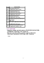
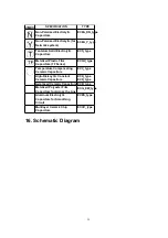
15.3. Symbolic Marks
The symbolic marks for resistors and capacitors which used in this circuits are classified as
following
Table-1
and
Table-2
.
15.3.1. RESISTORS
- Resistors without symbolic mark are FIXED CARBON FILM
RESISTORS (ERD-type).
- All resistors are 1/4 WATT, ±5 % TOLERANCE unless otherwise
designated in schematic diagrams.
Table-1
27
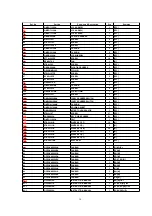
Summary of Contents for SX-KN6500
Page 8: ...10 Parts Location 8...
Page 30: ...30...
Page 37: ...C26 ECUV1H104ZFX 50V 0 1 1 MAIN SPC 37...
Page 49: ...L1 QLBG003A COIL 1 MAIN SPC 49...
Page 51: ...PCB18 SXPG232941 ACP P C B 1 EG EZ EB RTL M 51...
Page 55: ...R19 ERDS2TJ103 1 4W 10K 1 CPL SPC 55...
Page 63: ...X301 QSIG1I3000A 30MHZ CERAMIC OSCILLATOR 1 MAIN M 63...
Page 66: ...22 Manual Keyboard Parts and Control Panel Parts Location 66...
Page 67: ...67...


