


AIMA3000.FT5X Product User Manual
Technetix Group Limited
•
technetix.com
May/2016 - Version 1.0
12
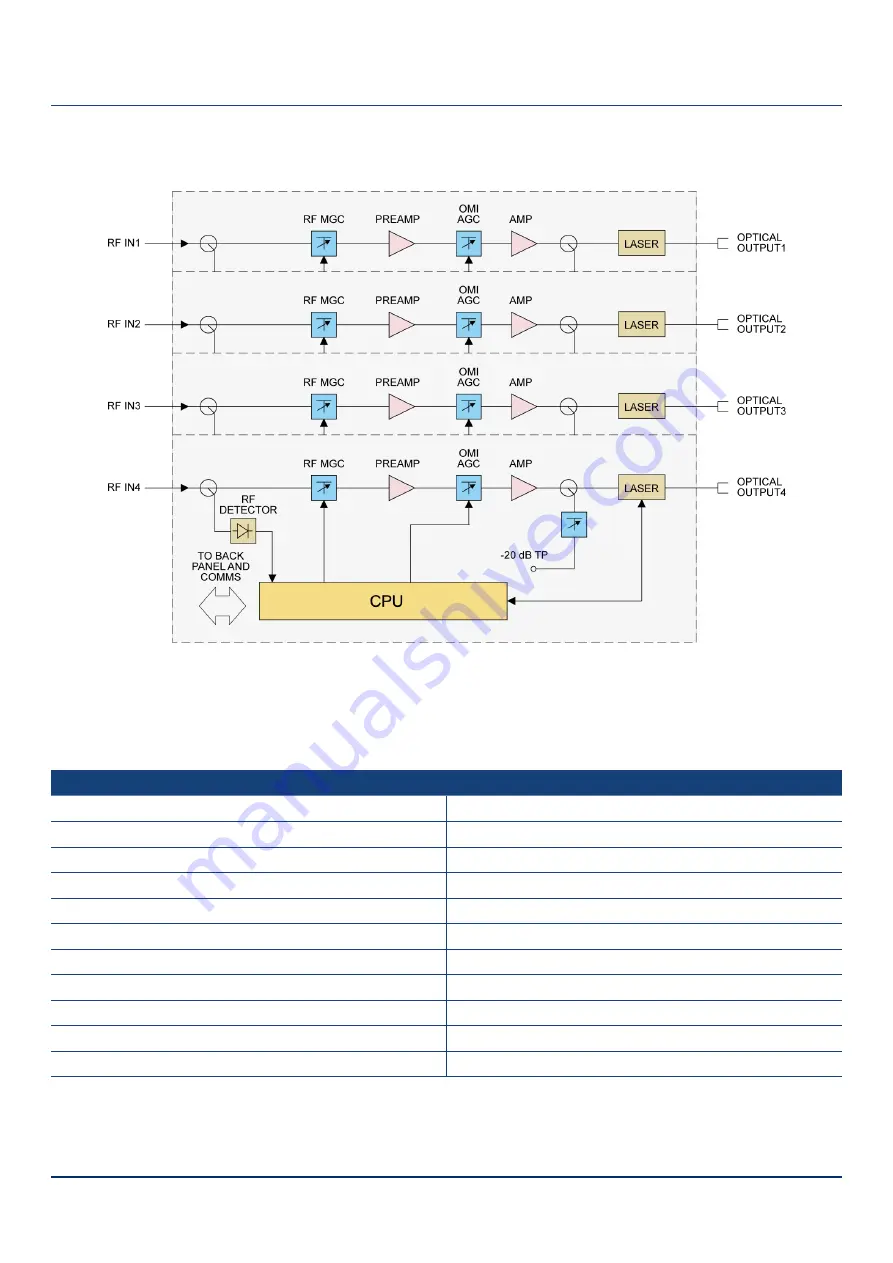
3.4 Block Diagram
Figure 3 1 Block diagram FT5X
Table 3 1 RT5S Block Diagram Glossary
Parameters
Glossary
-20 dB TP
-20 dB Test Point
RF IN
RF Input
RF MGC
RF Input Gain
PRE AMPLIFIER
Pre-Amplifier
OMI AGC
OMI Automatic Gain Control
AMP
Output Stage Amplifier
LASER
Laser
OPTICAL OUTPUT
Optical Output
TO BACK PLANE AND COMMS
Data Bus
CPU
Central Processing Unit
RF DETECTOR
RF level detector


