7b.On Wheels-Free Hoist
(A) Remove the column hooks, air cylinders,
springs and swivel blocks from the outside of
both crossmembers. Remove the air lines from
inside the crossmembers.
(B) Line up the holes in the tracks and
crossmembers, fit the four extension U-brackets
using the M10 x 25 mm long grade 8.8 screws
supplied with the wheels-free beam kit. Do not
tighten yet.
(C) Place the wheels-free crossmembers into the U-
brackets over the locating pins.
Note:
The crossmembers are not the same. The
operating handles must be on the power column side
of the hoist.
(D) Engage the interlock pins to lock the wheels-
free crossmembers and the hoist crossmembers
together. Adjust the U-brackets so the interlock
pins engage freely. Now fully tighten the M10
screws. Remove the wheels-free crossmembers
to tighten all the screws.
(E) Fit the wheel stops and drive-on ramps to the
outside of the U-brackets with the M10 x 20mm
long screws and nuts. Refer Fig.C. Refit the
wheels-free crossmembers.
wheels-free crossmember, down into the U-
brackets so that the crossmember is not leaning
out and does not wobble.
(G) Adjust the locating screws on the top inside
edge of the wheels-free crossmembers until the
crossmember is not leaning inward. Check the
interlock pins still engage freely.
8. Carefully remove the clutches (Fig. D) and the cable
retainers from the end of the crossmembers and
feed the cables through the ends of the
crossmembers and around the cable pulleys. Refit
the cable retainers. Place a clutch spring and guide
ferrule over the guide pin on the clutch and refit the
clutch to the crossmember.
Note:
The four clutches are preset for each corner and
must not be mixed up or damaged in any way.
9. Remove the clutch rods from the columns and offer
each column up to the crossmembers so that the
notches are on the outside in line with the column
hooks on the crossmembers.
Note:
The power column (which has two holes in the
back) must go on the crossmember beside the
hydraulic hose.
(A) On Wheels-Free Hoist
Fit a coiled hose, bulkhead connector and
elbow connector to the column furthest from the
power column.
(B) On All Hoists
Connect the bottom of the coiled tube inside the
column(s) to the connector(s) at the end of the
crossmember(s) inside the column. Feed the
guide tube(s) down through the top of the
column(s)and through the middle of the coiled
tube(s).
10.Remove the plastic plug from the end of the
hydraulic hose and pull hard on the cables to
extend the cylinder. Now feed the cable adjusting
screws through the top of each column and fit two
nuts to each screw. Leave the nuts loose.
11.Feed the clutch rods down through the top of the
columns. Hold the clutch square against the clutch
spring stop and lower the clutch rod through
the hole in the clutch and the guide bush just below
the clutch. Now check that the spring on the clutch
is still straight and is not buckled. Screw the clutch
rod into the base of the column while still holding
the clutch square. (If the clutch is not held square,
it will mark the clutch rod and cause the guide bush
to wear rapidly.) Tighten the nut on the top of the
rod sufficiently to tension the rod.
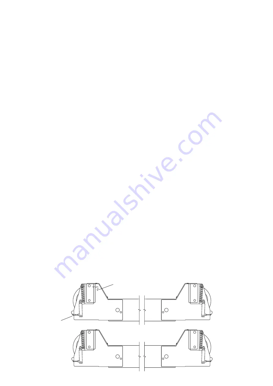
FIG. B
Power Crossmember
LIMIT SWITCH TRIGGER
TEE
CONNECTOR
Slave Crossmember
(F) Adjust the screws in the bottom outer edge of the
Summary of Contents for TEC 4000
Page 1: ...4000 4 Post 4 Tonne Hoist TEC4000 TEC4011 Wheels Free Beams...
Page 18: ......
Page 19: ......
Page 23: ...Page 22 Note...


