background image

(i)

Safety Summary

EM1-33033

Safety Summary

Personal safety in handling or maintaining the equipment is extremely important.  Warnings and Cautions
necessary for safe handling are included in this manual.  All warnings and cautions contained in this
manual should be read and understood before handling or maintaining the equipment.
Do not attempt to effect repairs or modifications to this equipment.  If a fault occurs that cannot be rectified
using the procedures described in this manual, turn off the power, unplug the machine, then contact your
authorized TOSHIBA TEC representative for assistance.

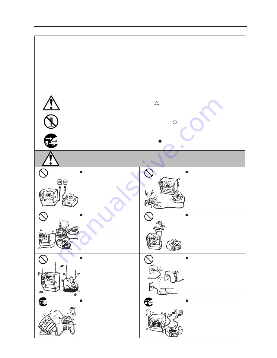
Meanings of Each Symbol

This symbol indicates warning items (including cautions).
Specific warning contents are drawn inside the     symbol.
(The symbol on the left indicates a general caution.)

This symbol indicates prohibited actions (prohibited items).
Specific prohibited contents are drawn inside or near the     symbol.
(The symbol on the left indicates “no disassembling”.)

This symbol indicates actions which must be performed.
Specific instructions are drawn inside or near the    symbol.
(The symbol on the left indicates “disconnect the power cord plug from the outlet”.)

   Do not use voltages other than the
voltage (AC) specified on the rating
plate, as this may cause fire or
electric shock.

Any other than the
specified AC voltage
is prohibited.

WARNING

This indicates that there is the risk of death or serious injury if the
machines are improperly handled contrary to this indication.

Prohibited

   Do not plug in or unplug the power
cord plug with wet hands as this may
cause electric shock.

   Do not place metal objects or
water-filled containers such as flower
vases, flower pots or mugs, etc. on
top of the machines.  If metal objects
or spilled liquid enter the machines,
this may cause fire or electric
shock
.

   If the machines share the same
outlet with any other electrical
appliances which consume large
amounts of power, the voltage will
fluctuate widely each time these
appliances operate.  Be sure to
provide an exclusive outlet for the
machine as this may cause the
machines to malfunction.

   Do not insert or drop metal,
flammable or other foreign objects into
the machines through the ventilation
slits, as this may cause fire or electric
shock
.

Prohibited

Prohibited

Prohibited

   Do not scratch, damage or modify
the power cords.  Also, do not place
heavy objects on, pull on, or exces-
sively bend the cords, as this may
cause fire or electrical shock.

Prohibited

   Continued use of the machines in an
abnormal condition such as when the
machines are producing smoke or
strange smells may cause fire or elec-
tric shock
.  In these cases, immedi-
ately turn off the power switches and
disconnect the power cord plugs from
the outlet.  Then, contact your author-
ized TOSHIBA TEC representative for
assistance.

Disconnect
the plug.

   If the machines are dropped or their
cabinets damaged, first turn off the
power switches and disconnect the
power cord plugs from the outlet, and
then contact your authorized
TOSHIBA TEC representative for
assistance.  Continued use of the
machine in that condition may cause
fire or electric shock.

Disconnect
the plug.

Summary of Contents for TEC EM1-33033

Page 1: ...TEC Thermal Printer B 470 QQ SERIES Owner s Manual Mode d emploi Bedienungsanleitung Manual de instrucciones Gebruikershandleiding Owner s Manual...

Page 2: ...own expense for USA only Changes or modifications not expressly approved by manufacturer for compliance could void the user s authority to operate the equipment This Class A digital apparatus meets al...

Page 3: ...indication Prohibited Do not plug in or unplug the power cord plug with wet hands as this may cause electric shock Do not place metal objects or water filled containers such as flower vases flower po...

Page 4: ...ribbons DO NOT STORE the paper or ribbons where they might be exposed to direct sunlight high tem peratures high humidity dust or gas Ensure the printer is operated on a level surface Any data stored...

Page 5: ...LE OF CONTENTS Page 1 INTRODUCTION 1 1 1 1 Applicable Model 1 5 1 2 Accessories 1 5 2 SPECIFICATIONS 2 1 2 1 Printer 2 1 2 2 Options 2 2 2 3 Media 2 3 2 4 Ribbon 2 3 3 OVERVIEW 3 1 3 1 Front Rear View...

Page 6: ...ribbon saver rewinder strip mechanism and external media supply you will have a printer to suit a wide variety of applications and environments This manual contains general set up and maintenance inf...

Page 7: ...nches Batch Continuous Strip On demand and Cut modes Both cut and strip modes are available only when their respective modules are fitted 16 characters x 1 line 291 mm width x 460 mm depth x 308 mm he...

Page 8: ...n assist in finding one for you This is a paper guide exclusively used for fanfold paper Attaching it in place of the standard pa per guide allows the printer to print on fanfold paper A flash ROM car...

Page 9: ...th B plus inter label gap length E exceeds 35 mm i e label pitch should be greater that 35 mm 4 When rewinding the media onto the take up spool in batch mode the max outer roll diameter should be 180...

Page 10: ...rs when the media ribbon ends or the printer does not operate correctly FEED key Feeds paper RESTART key Resets the printer when paused or when an error occurs Used to set the threshold Refer to page...

Page 11: ...N OFF ON 2 OFF OFF ON ON 2400 BPS 4800 BPS 9600 BPS 19200 BPS 1 bit 2 bit 7 bit 8 bit without with EVEN ODD XON XOFF No XON is output at the power on time No XOFF is output at the power off time READY...

Page 12: ...this product If using another cable it should conform to the following specifications For more details please contact your local TOSHIBA TEC service representative Centronics Interface 36 pins Male Pr...

Page 13: ...lever must be set to position 1 This ensures that the print head and the pinch roller are closed 3 Turn the locking ring counter clockwise and remove the supply holder from the supply shaft NOTE Dono...

Page 14: ...paper holders of the media guide adjust the media guides to the media width and tighten the locking screw 8 Check that the media path through the printer is straight The media should be centered under...

Page 15: ...g 6 5 Media Guide Screw T 4x8 3 Attach the media guide back in position NOTE Do not lose the removed upper plates because they are required when using the label rolled with labels facing inside 9 Set...

Page 16: ...sor position to that of the black mark the upper hole indicates the position of the black mark sensor NOTE Make sure to set the sensor to detect the center of the black mark otherwise a paper jam erro...

Page 17: ...the paper counter clockwise around the spool as this is the direction it rotates 3 Rotate the take up spool anti clockwise a few times to take up any slack in the backing paper Fig 6 9 NOTES 1 The bac...

Page 18: ...selection switch to the REWINDER position 3 Follow the procedure for strip type 4 Adjustment If the label skews when using built in rewinder unit turn the adjustment knob of the rewinder guide plate...

Page 19: ...these are standard media and direct thermal media a chemically treated surface DO NOT LOAD a ribbon when using a direct thermal media 1 When using a narrow width ribbon slide the ribbon stoppers along...

Page 20: ...p place 5 Before inserting or removing the card make sure that the power switch is turned off 6 Thefollowingflashcardscanbeused The1MB cardisreadonlyandthe4MBcardcanread write Fig 8 1 Flash Memory Car...

Page 21: ...es as this might flatten that side causing erratic media advance and poor print quality Store the media in plastic bags and always reseal after opening Unprotected media can get dirty and the extra ab...

Page 22: ...disconnect the power cord prior ot performing any maintenance 2 Do not use any tool that may damage the print head 3 DO NOT POUR WATER directly onto the printer 10 1 Cleaning To help retain the high...

Page 23: ...nit can be caused by wear or residual glue from label stock on the cutter Do not use none specified media in the cutter If you get frequent jams in the cutter contact your Authorized Service represent...

Page 24: ...ide 3 Remove the jammed paper and trash 4 Clean the cutter with dry cloth 5 Assembling is reverse order of removal Fig 10 3 Fixed Cutter Cutter Unit Swing Cutter Screw Media Guide Cutter Cover White S...

Page 25: ...osition after setting the threshold adjust the feed gap sensor in the system mode Reset the threshold again Make sure that the transmissive sensor for pre printed labels is selected in the feed and is...

Page 26: ...firmware version 2 5 or earlier 1 Turn the power on 2 Load the pre printed label Any position 3 Press the PAUSE key once 4 Hold down the PAUSE key for more than 3 seconds and it will begin to feed Af...

Page 27: ...ctly Press the RESTART key 2 Remove the cause of the jam and replace the media correctly Press the RESTART key 3 Turn the power off then on again Select the correct sensor Feed the media 4 Adjust the...

Page 28: ...ur Authorized Service repre sentative if necessary Correct the command and re send it again Turn the power off then on again If the problem still exists turn the power off and contact your Authorized...

Page 29: ...print head Call your Authorized Service representative if necessary 1 Dirty print head Clean the print head 2 Bad or faulty ribbon Replace ribbon 3 Poor media quality Change media type 1 Plug power c...

Page 30: ......

Page 31: ......

Page 32: ...PRINTED IN JAPAN EM1 33033 E...

Reviews: