E6-1
6. INSTALLATION PROCEDURE
ENGLISH VERSION EO1-33016
6. INSTALLATION PROCEDURE
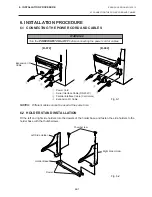
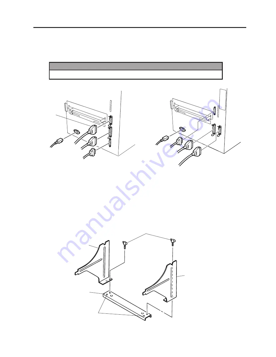
6.1 CONNECTING THE POWER CORD AND CABLES
6.1 CONNECTING THE POWER CORD AND CABLES
Fig. 6-1
Fig. 6-2
NOTES:
Different cables cannot be used at the same time.
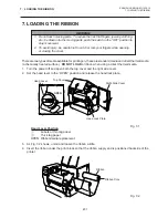
6.2 HOLDER STAND INSTALLATION
Fit the left and right side holders into the dowels of the holder base and fasten the side holders to the
holder base with the thumbscrews.
Left Side Holder
Thumbscrew
Right Side Holder
Dowel
Holder Base
WARNING!
Turn the POWER SWITCH to OFF before connecting the power cord or cables.
[B-672]
[B-682]
Expansion I/O
Cable
4
3
2
1
1
2
3
4
1
Power Cord
2
Serial Interface Cable (RS-232C)
3
Parallel Interface Cable (Centronics)
4
Expansion I/O Cable
Summary of Contents for B-680 Series
Page 3: ...TEC Thermal Printer B 670 680 SERIES Owner s Manual ...
Page 34: ...I imprimante Transfert Thermique TEC B 670 680 SERIES Mode d emploi ...
Page 65: ...TEC Thermo Thermotransfer Drucker B 670 680 SERIES Bedienungsanleitung ...
Page 96: ...Impresora térmica TEC B 670 680 SERIES Manual de instrucciones ...
Page 127: ...TEC Thermische Drukker B 670 680 SERIES Gebruikershandleiding ...


