background image

10-1

10. GENERAL MAINTENANCE

EM1-33033

10.1 Cleaning

10. GENERAL MAINTENANCE

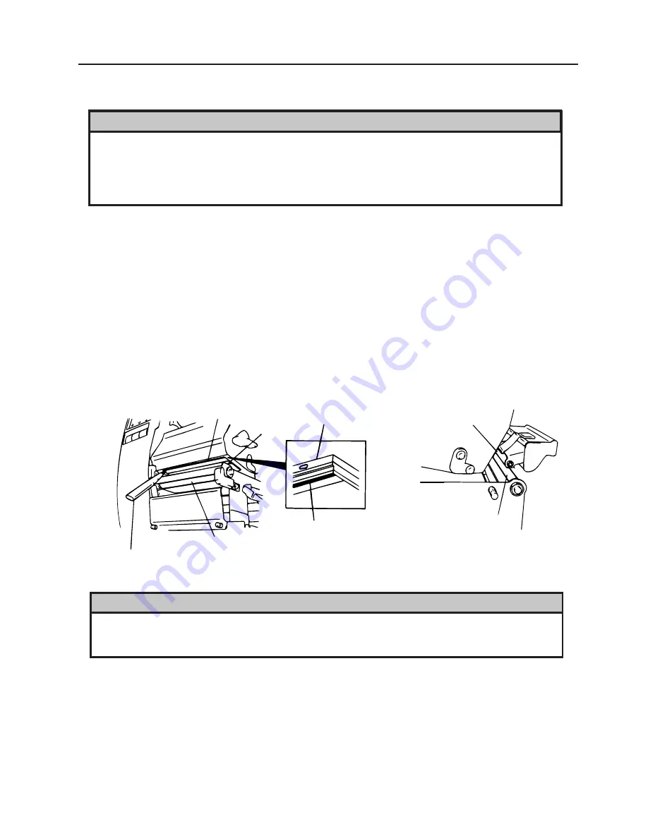
Fig. 10-1

Pinch Roller

Feed Roller

Print Head

Element

Element

Print Head

Platen

Print Head Cleaner
(24089500013)

WARNING!

1. Be careful when handling the print head as it becomes very hot.
2. Care must be taken not to injure yourself with the printer paper cutter.
3. Do not touch moving parts.  To reduce the risk that fingers, jewelry, clothing, etc., be drawn

into the moving parts, push the switch in the “OFF” position to stop movement.

4. To avoid injury, be careful not to catch or jam your fingers while opening or closing the cover.

WARNING!

1. Be sure to disconnect the power cord prior ot performing any maintenance.
2. Do not use any tool that may damage the print head.
3. DO NOT POUR WATER directly onto the printer.

10.1 Cleaning

To help retain the high quality and performance of your printer it should be regularly cleaned.  The
greater the usage of the printer, the more frequent the cleaning.  (i.e. low usage=weekly : high usage=daily).
A print head cleaner is not enclosed with the printer, so please inquire at your local distributor.
1.

Turn the power off.

2.

Open the top cover.

3.

Turn the head lever to raise the print head.

4.

Remove the ribbon and media.

5.

Clean the element of print head with print head cleaner.

6.

Wipe the platen, feed roller and pinch roller with a cleaner moistened with alcohol.
Remove dust or foreign substances from the internal part of the printer, if any.

Summary of Contents for B-470-QQ Series

Page 1: ...TEC Thermal Printer B 470 QQ SERIES Owner s Manual Mode d emploi Bedienungsanleitung Manual de instrucciones Gebruikershandleiding Owner s Manual ...

Page 2: ... own expense for USA only Changes or modifications not expressly approved by manufacturer for compliance could void the user s authority to operate the equipment This Class A digital apparatus meets all requirements of the Canadian Interference Causing Equipment Regulations Cet appareil numérique de la classe A respecte toutes les exigences du Règlement sur le matériel brouilleur du Canada for CAN...

Page 3: ...s indication Prohibited Do not plug in or unplug the power cord plug with wet hands as this may cause electric shock Do not place metal objects or water filled containers such as flower vases flower pots or mugs etc on top of the machines If metal objects or spilled liquid enter the machines this may cause fire or electric shock If the machines share the same outlet with any other electrical appli...

Page 4: ... ribbons DO NOT STORE the paper or ribbons where they might be exposed to direct sunlight high tem peratures high humidity dust or gas Ensure the printer is operated on a level surface Any data stored in the memory of the printer could be lost during a printer fault Try to avoid using this equipment on the same power supply as high voltage equipment or equip ment likely to cause mains interference...

Page 5: ...BLE OF CONTENTS Page 1 INTRODUCTION 1 1 1 1 Applicable Model 1 5 1 2 Accessories 1 5 2 SPECIFICATIONS 2 1 2 1 Printer 2 1 2 2 Options 2 2 2 3 Media 2 3 2 4 Ribbon 2 3 3 OVERVIEW 3 1 3 1 Front Rear View 3 1 3 2 Operation Panel 3 1 4 DIP SWITCH FUNCTIONS 4 1 5 INSTALLING THE PRINTER 5 1 6 LOADING THE MEDIA 6 1 7 LOADING THE RIBBON 7 1 8 INSERTING THE OPTIONAL FLASH MEMORY CARD 8 1 9 CARE HANDLING OF...

Page 6: ...c ribbon saver rewinder strip mechanism and external media supply you will have a printer to suit a wide variety of applications and environments This manual contains general set up and maintenance information and should be read carefully to help gain maximum performance and life from your printer For most queries please refer to this manual and keep it safe for future reference 1 1 Applicable Mod...

Page 7: ...inches Batch Continuous Strip On demand and Cut modes Both cut and strip modes are available only when their respective modules are fitted 16 characters x 1 line 291 mm width x 460 mm depth x 308 mm height 17 kg without media and ribbon UPC E UPC E 2digits UPC E 5digits UPC A UPC A 2digits UPC A 5digits JAN8 JAN13 EAN8 EAN8 2digits EAN8 5digits EAN13 EAN13 2digits EAN13 5digits MSI ITF NW 7 CODE39...

Page 8: ...an assist in finding one for you This is a paper guide exclusively used for fanfold paper Attaching it in place of the standard pa per guide allows the printer to print on fanfold paper A flash ROM card 1MB and 4MB for storing logos writable characters and formats Type B 4205 QM B 4700 IO QM B 4905 H QM B 4905 R QM B 4905 FF QM Source See NOTE 1 See NOTE 3 See NOTE 1 See NOTE 1 See NOTE 1 See NOTE...

Page 9: ...th B plus inter label gap length E exceeds 35 mm i e label pitch should be greater that 35 mm 4 When rewinding the media onto the take up spool in batch mode the max outer roll diameter should be 180 mm 5 Use of rough media for the ribbon saving issue may cause ribbon smudges Fig 2 1 25 4 999 0 23 4 997 0 50 8 112 0 47 8 109 0 2 0 20 0 2 0 10 0 10 0 104 0 21 4 384 0 21 4 896 0 23 4 384 0 23 4 896 ...

Page 10: ...urs when the media ribbon ends or the printer does not operate correctly FEED key Feeds paper RESTART key Resets the printer when paused or when an error occurs Used to set the threshold Refer to page 10 4 PAUSE key Pauses printing Message display shows PAUSE and an unprinted count Used to set the threshold Refer to page 10 4 Fig 3 2 Fig 3 1 Front View Rear View Top Cover Supply Window Message Dis...

Page 11: ...ON OFF ON 2 OFF OFF ON ON 2400 BPS 4800 BPS 9600 BPS 19200 BPS 1 bit 2 bit 7 bit 8 bit without with EVEN ODD XON XOFF No XON is output at the power on time No XOFF is output at the power off time READY BUSY DTR No XON is output at the power on time No XOFF is output at the power off time READY BUSY RTS XON is output at the power on time XOFF is output at the power off time XON XOFF READY BUSY XON ...

Page 12: ... this product If using another cable it should conform to the following specifications For more details please contact your local TOSHIBA TEC service representative Centronics Interface 36 pins Male Printer Side Connector Pin Signals Expansion I O Interface 24 pins Male Printer Side Connector Pin Signals RS 232C Interface DB 25S 25 pins Male DB 9P Metric screw type Connector to PC Connector to Pri...

Page 13: ...d lever must be set to position 1 This ensures that the print head and the pinch roller are closed 3 Turn the locking ring counter clockwise and remove the supply holder from the supply shaft NOTE Donotturntheforcethelockingringtoofarcounterclockwiseoritmaycomeoffthesupplyholder Fig 6 2 WARNING 1 Do not touch moving parts To reduce the risk that fingers jewelry clothing etc be drawn into the movin...

Page 14: ... paper holders of the media guide adjust the media guides to the media width and tighten the locking screw 8 Check that the media path through the printer is straight The media should be centered under the print head NOTE When using the label rolled with labels facing outside please remove the upper plates of both paper holders using the following procedure Failure to do this may cause a paper jam...

Page 15: ...ig 6 5 Media Guide Screw T 4x8 3 Attach the media guide back in position NOTE Do not lose the removed upper plates because they are required when using the label rolled with labels facing inside 9 Set the black mark feed gap sensor to the correct position by turning the adjusting knob Turning the knob right will move the sensor towards the center of the media while turning left will move it away f...

Page 16: ...nsor position to that of the black mark the upper hole indicates the position of the black mark sensor NOTE Make sure to set the sensor to detect the center of the black mark otherwise a paper jam error could occur Setting the feed gap sensor position 1 Adjust the sensor to detect on the gap the lower hole indicates the position of the feed gap sensor Fig 6 7 Black Mark Black Mark Sensor Feed Gap ...

Page 17: ... the paper counter clockwise around the spool as this is the direction it rotates 3 Rotate the take up spool anti clockwise a few times to take up any slack in the backing paper Fig 6 9 NOTES 1 The backing paper is easier to feed back to the take up spool if the front plate is removed 2 When fitting the tace up clip the longer side of the clip should be fitted into the shallow groove on the take u...

Page 18: ...e selection switch to the REWINDER position 3 Follow the procedure for strip type 4 Adjustment If the label skews when using built in rewinder unit turn the adjustment knob of the rewinder guide plate to correct the label feed Clockwise turn moves the rewinder guide plate forward and counterclockwise moves it backward When labels skew to the right Loosen the SM 4x8 sems screw with a philips head s...

Page 19: ... these are standard media and direct thermal media a chemically treated surface DO NOT LOAD a ribbon when using a direct thermal media 1 When using a narrow width ribbon slide the ribbon stoppers along the shafts to a position where the ribbon will be centered when it is fitted When changing from a narrow width to a wider one rotate the ribbon stoppers by 90 push them back to the correct position ...

Page 20: ...mp place 5 Before inserting or removing the card make sure that the power switch is turned off 6 Thefollowingflashcardscanbeused The1MB cardisreadonlyandthe4MBcardcanread write Fig 8 1 Flash Memory Card CAUTION To protect memory cards discharge static electricity from your body by touching the printer rear cover prior touching the memory cards WARNING Turn the power OFF when inserting or removing ...

Page 21: ...des as this might flatten that side causing erratic media advance and poor print quality Store the media in plastic bags and always reseal after opening Unprotected media can get dirty and the extra abrasion from the dust and dirt particles will shorten the print head life Store the media and ribbon in a cool dry place Avoid areas where they would be exposed to direct sunlight high temperature hig...

Page 22: ...o disconnect the power cord prior ot performing any maintenance 2 Do not use any tool that may damage the print head 3 DO NOT POUR WATER directly onto the printer 10 1 Cleaning To help retain the high quality and performance of your printer it should be regularly cleaned The greater the usage of the printer the more frequent the cleaning i e low usage weekly high usage daily A print head cleaner i...

Page 23: ...unit can be caused by wear or residual glue from label stock on the cutter Do not use none specified media in the cutter If you get frequent jams in the cutter contact your Authorized Service representative Fig 10 2 Media Sensor Media Guide Plate Black Screw HAA 0004001 10 2 Covers and Panels The covers should be cleaned by wiping with a dry cloth or a cloth slightly dampened with a mild detergent...

Page 24: ...uide 3 Remove the jammed paper and trash 4 Clean the cutter with dry cloth 5 Assembling is reverse order of removal Fig 10 3 Fixed Cutter Cutter Unit Swing Cutter Screw Media Guide Cutter Cover White Screw 24741710304 WARNING 1 Be sure to turn the power off before cleaning the cutter unit 2 The cutters are sharp and care should be taken not to injure yourself when cleaning ...

Page 25: ...position after setting the threshold adjust the feed gap sensor in the system mode Reset the threshold again Make sure that the transmissive sensor for pre printed labels is selected in the feed and issue commands 1 The printer is in stand by 2 Load a media roll in the usual way 3 Press the PAUSE key 4 The printer enters the pause mode 5 Press and hold the PAUSE key for at least 3 seconds in the p...

Page 26: ...r firmware version 2 5 or earlier 1 Turn the power on 2 Load the pre printed label Any position 3 Press the PAUSE key once 4 Hold down the PAUSE key for more than 3 seconds and it will begin to feed After it has fed the 2 label release the PAUSE key 5 Press the RESTART key for ON LINE mode 6 Threshold setting is now completed NOTES 1 If the PAUSE key is not held down for more than 3 seconds in PAU...

Page 27: ...ectly Press the RESTART key 2 Remove the cause of the jam and replace the media correctly Press the RESTART key 3 Turn the power off then on again Select the correct sensor Feed the media 4 Adjust the sensor position Press the RESTART key 5 Turn the power off then on again Set the correct media size Feed the media 6 Set the threshold see page 10 4 Else Turn the power off and call your Authorized S...

Page 28: ...our Authorized Service repre sentative if necessary Correct the command and re send it again Turn the power off then on again If the problem still exists turn the power off and contact your Authorized Service representative Media is jammed in the cutter An error has occurred when loading data onto a flash memory card An error has occurred while formatting a flash memory card No more data can be sa...

Page 29: ...e print head Call your Authorized Service representative if necessary 1 Dirty print head Clean the print head 2 Bad or faulty ribbon Replace ribbon 3 Poor media quality Change media type 1 Plug power cord into an AC socket 2 Check the circuit breakers or fuses 3 Plug another appliance into the AC socket to check if there is power supplied Call your Authorized Service representative if necessary Ch...

Page 30: ......

Page 31: ......

Page 32: ...PRINTED IN JAPAN EM1 33033 E ...

Reviews: