English
English
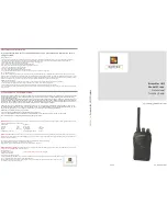
Setting up the TEAM TS-6M
1) Installation of a CB antenna
The antenna is one of the most critical parts in the setup. The type of antenna and its loca-
tion has a great effect on the range of operation. Please consider the following criteria for
selection of the best location and installation of your antenna:
> Make sure that the antenna is designed for radio operation on 27 MHz.
> The location of the antenna should be as high as possible without any obstacles nearby.
> The aerial cable should not be damaged and the plugs should be properly connected.
> Make sure that the antenna cable is not bent.
> The bigger the mechanical size of the antenna, the higher the range of operation.
When you install a mobile antenna please note the following advices:
> The antenna should be fixed in the center of a big body-part, e.g. the trunk.
> The mobile antenna coil should have the closest possible contact with a conducting metallic
surface of the bodywork of the car.
There are also some other possibilities to fix the antenna onto the car without the necessity
to drill a hole into the bodywork of your car, e.g. mounting the antenna onto the gutter, mount-
ing the antenna onto a holder on the cover of the boot or using an antenna with a magnetic
foot or using a windscreen antenna.
For base-station operation we recommend a stationary antenna on the roof, for example the
TEAM ECO 050 or ECO 200.
> Please don't mount the CB antenna nearby a radio or TV antenna to prevent interference
of radio or TV reception.
> Keep an eye on power lines running along nearby when mounting the antenna on the roof.
" DANGER "
> The base-station antenna has to be connected via a lightning arrester.
> All connected cables including the antenna cable must not exceed a length of 3 m.
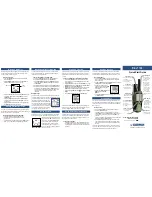
2) Aerial Connection
Before pressing the transmit key, a suitable aerial must be connected. The PL259 plug of the
aerial cable ( coax ) is connected to the SO239 socket ( 14 ) on the rear panel. Make sure,
that all plugs are firmly tightened and properly soldered. Insufficient connections can damage
the radio and will reduce the range of operation.
The antenna should be matched with the radio, otherwise a part of the transmit power will be
reflected at the antenna and will not be radiated. This reduces the range of operation. The
matching of antenna to radio, is performed by a length adjustment of the antenna radial in
aim for a minimal SWR ratio which can be measured by a SWR meter,e.g. TEAM SWR
1180P. After the measurement the SWR meter should be removed from the antenna line.
3) Installation in the car
When you want to fix the unit in your car, you can either fasten it with the help of the includ-
ed mounting bracket below the dashboard. Always mount the transceiver where the switch-
es are easily accessible. Other important points to consider for a correct mounting position
are:
TABLE OF CONTENTS
Setting up the TEAM TS-6M
1) Installation of a CB antenna
13
2) Aerial Connection
13
3) Installation in the car
13 - 14
4) Microphone DM-906T
14
5) Power source
14
Operation of the TEAM TS-6M
1) Switching on [ Off / Vol ]
15
2) Squelch [
SQ / ASQ
] 15
3) Channel selection [
] [
]
15
4) Modulation selection [
Mode
]
15 - 16
5) Norm selection
16
6) Transmitting
16
7) Call tone
16
8) Priotitiy Channels 9 / 19
16
9) Receipt-Signal Sensitivity [
RFG
]
17
10) Signal meter
17
11) External signal meter jack
17
Additional Information
1) Safety Instructions
17
2) General Precautions
17
3) Servicing
17
4) Conformity
17
Channel Frequencies
18
Specifications
19
Schematic Diagram & PCB layout
20 - 23
12
13
ts-6m_manual.qxp 06.01.2010 11:52 Seite 12