replacing. Before removing the hammers note the
size and position of the spacers. Remove the bolt
retaining the hammers and either turn them or
reposition them using the unused pivot hole. Refit the
bolt making sure the spacers and blade bushes are
replaced in the correct order.
11.4 Drum removal
NOTE.
This operation requires two persons.
To remove the drum, dismantle the belt guards then
slacken and remove the belts. Swing the motor
assembly around so that it is well clear of the drum
and restrain it in that position. Turn the drum so that
the large hole in its periphery is at the top. Suspend
the drum from the spiral bar inside the lifting hole
using a certified lifting strop or chain with a load rating
in excess of 520kg.
Remove the two lower rear drum retainers and roller
guards so that is it possible to slide the drum
rearwards. Slacken the two bolts holding the top
bearing channel in place and carefully remove it,
ensuring that the loader is just taking the weight of the
drum as the bolts are loosened. Raise the drum
slightly and slide it rearwards, away from the machine.
Reassembly is a reverse of the above procedure.
11.5 Drum mountings
The lower rollers which support the drum are mounted
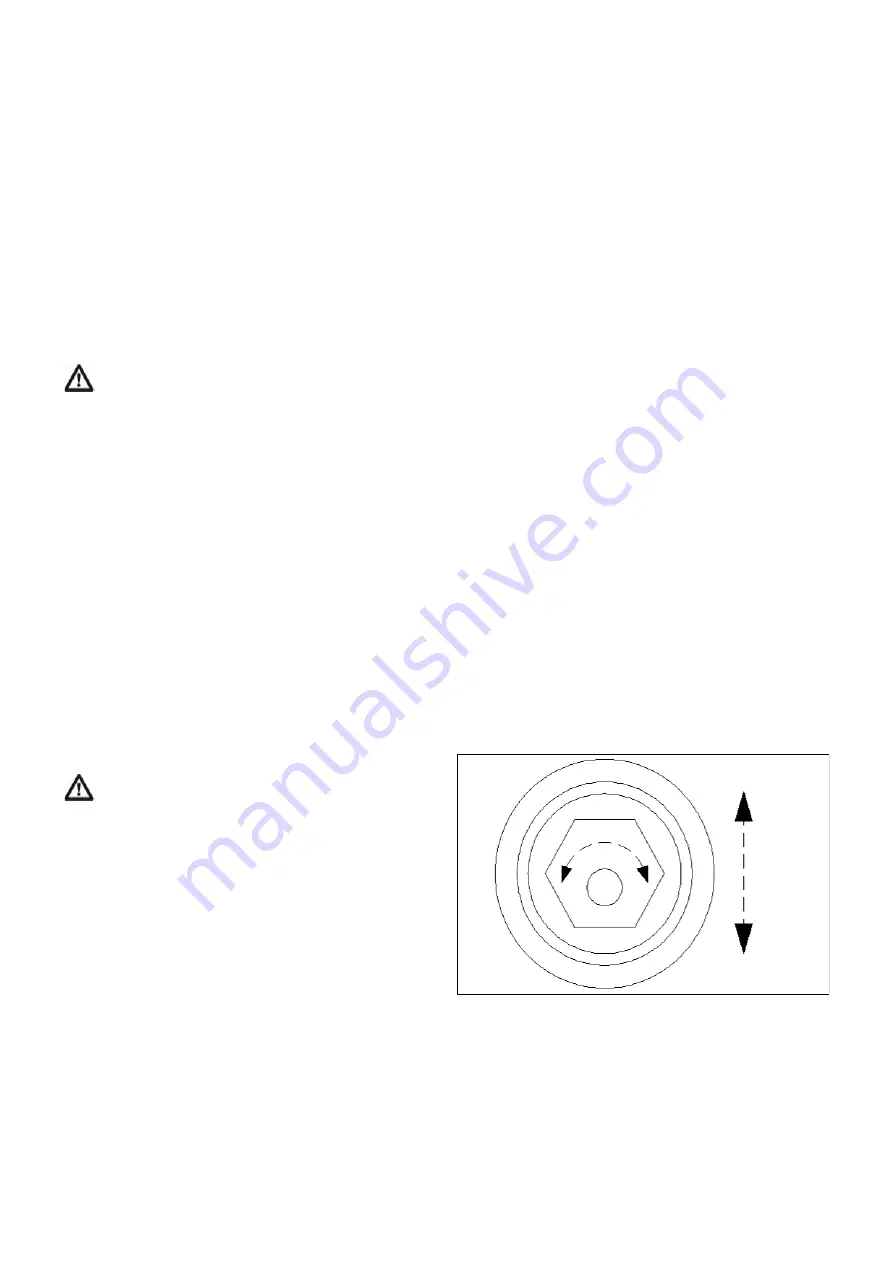
on eccentric hexagonal bosses - see Fig. 6. By
rotating these bosses, it is possible to centralise the
drum and adjust the clearance between the drum and
back plate at the bottom. The roller at the top of the
drum can be adjusted by moving the channel in its
slots. No adjustment is normally required as the
rollers are correctly positioned during factory
assembly. The clearance between the drum and back
plate should be 10 - 15mm.
Fig. 6 Eccentric Drum Mountings
11.6 Screen replacement (404M & 505M only)
Undo the six bolts retaining the screen to the back
plate. Rotate and slide the screen towards the rear of
the machine until it clears the rotor. Select the screen
to give the desired chop length and fit in the reverse
order of the above.
Fan speed can be controlled using the control knob at
the base of the oil cooler. Turning the knob in a
clockwise direction reduces fan speed.
Should oil temperature increase to 45 degrees Celsius
the oil cooler will automatically begin to operate. The
cooler will automatically reverse for a short time every
fifteen minutes to keep the cooler screen clear of
debris.
To stop fan operation, reduce PTO speed gradually
and when at idle disengage the PTO. Allow 3 minutes
for the rotor and fan to stop turning, turn the tractor
engine off and remove the ignition key before
disconnecting ducting from the fan outlet.
9.4 Blockage removal
WARNING.
Never begin to unblock a machine
until the PTO has been disengaged, the engine
stopped, the key removed from the ignition, and the
machine has come to rest.
Should the fan or ducting become blocked, use the
blockage removal tool loosen material inside and pull it
out.
10.0 USE ON THE PUBLIC HIGHWAY
If the machine is to be transported along the public
highway (any road where the public have access)
behind the tractor it will be necessary to comply with
local road traffic legislation as the machine is likely to
obscure the rear light units of the tractor.
Failure to comply with road traffic legislation may lead
to prosecution by local law enforcement agencies and
could also result in a road traffic accident.
11.0 MAINTENANCE
11.1 Safety
WARNING.
Never open the guards surrounding
the driveline or fan unless the PTO has been
disengaged, the engine has been stopped, the key
removed and the machine come to rest.
The fan and rotor will take approximately 3 minutes to
come to rest from operating speed.
11.2 Blades
When carrying out maintenance work on the blades,
wedge the rotor to prevent it from turning. Always
keep your hands away from the edges of blades
particularly new ones, as they are extremely sharp. A
leather glove will give some protection against minor
cuts.
IMPORTANT.
When replacing blade retaining bolts,
clean the threaded section and treat with a
threadlocking compound. The bolt should be
tightened to a torque of 150Nm (112lb/ft).
11.3 Hammers (404M & 505M only)
Hammers will wear with use and are designed to give
four different cutting surfaces before needing
8


