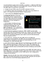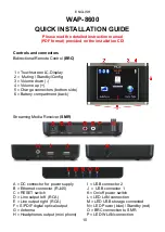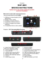
A = DC connector for power supply
B = Ethernet connector (RJ-45)
C = RESET switch
D = Line output left (RCA)
E = Line output right (RCA)
F = S/PDIF digital optical output
G = Antenna
H = Headphones output (mini phono)
I = USB connector 2
J = USB connector 1
K = On/off power switch
L = LED LAN connection
M = LED USB storage connected
N = LED Power (blue)/ Standby (red)
O = BRC connection to SMR
P = LED WLAN connection
ENGLISH
WAP-8600
QUICK INSTALLATION GUIDE
Please read the detailed instruction manual
(PDF format) provided on the installation CD!
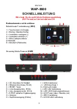
Controls and connectors
Bidirectional Remote Control
(BRC)
Streaming Media Receiver
(SMR)
10
1 = Touchscreen LC-Display
2 = Muting / Standby/Config
3 = Volume down (-)
4 = Volume up (+)
5 = Charge connectors (bottom side)
6 = Battery compartment (back)


