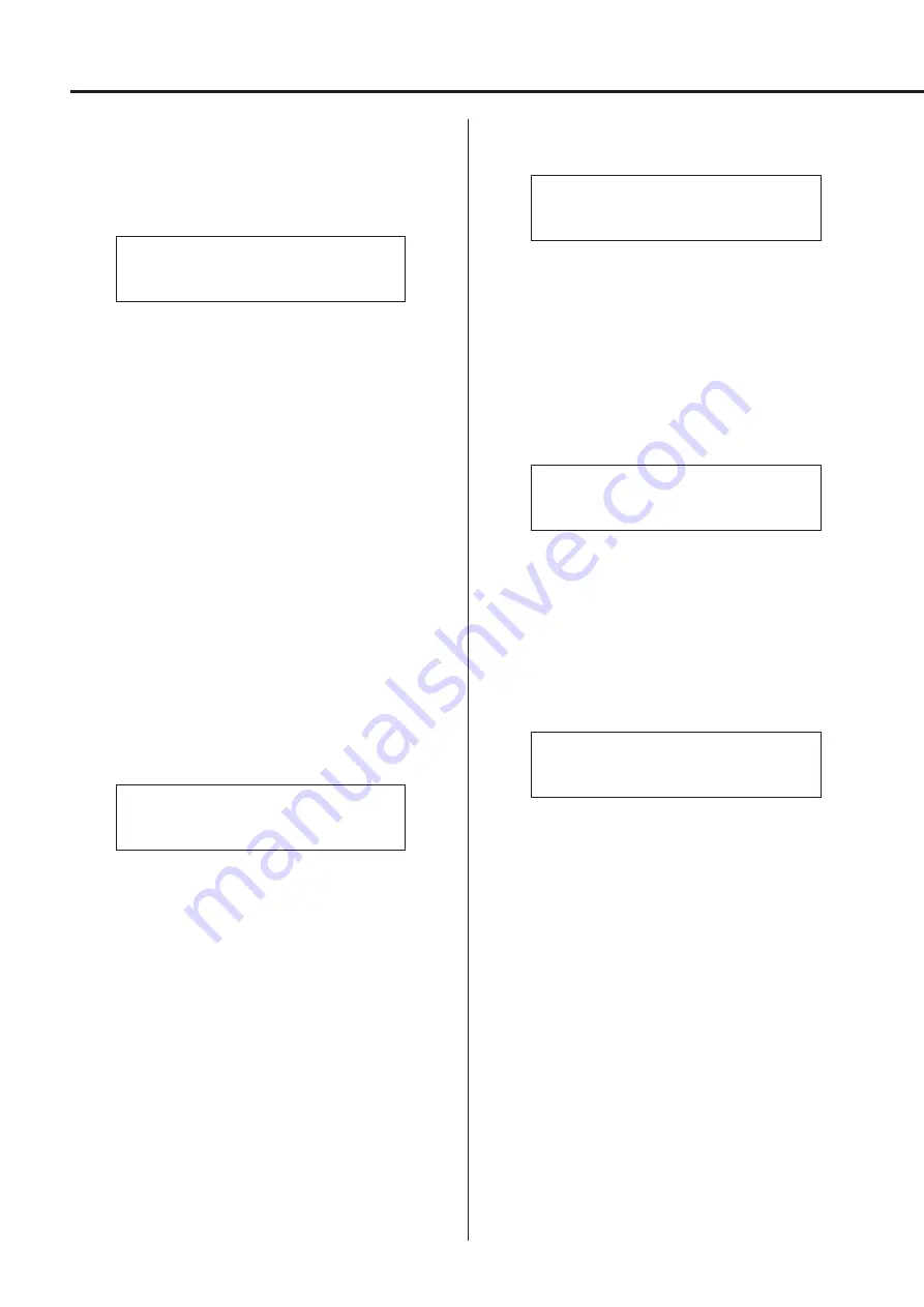
20
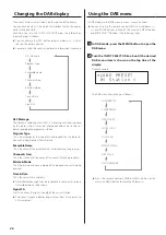
Upconversion
Use to activate the upconversion circuit when receiving PCM format
signals.
o
See page 15 for the relationships between input sampling fre-
quencies and sampling frequencies after upconversion.
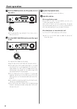
*UPCONVERT
> OFF
OFF
The original input signal is sent directly to the D/A converter
without upconversion.
2Fs
If the input audio signal is less than 2× a standard sampling fre-
quency (32, 44.1 or 48 kHz), it is upconverted 2× and then sent to
the D/A converter.
4Fs
If the input audio signal is less than 4× a standard sampling fre-
quency (32, 44.1 or 48 kHz), it is upconverted 4× and then sent to
the D/A converter.
8Fs
If the input audio signal is less than 8× a standard sampling fre-
quency (32, 44.1 or 48 kHz), it is upconverted 8× and then sent to
the D/A converter.
DSD
The input source is converted to DSD digital format, and then
sent to the D/A converter.
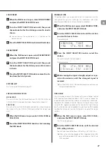
PCM digital filter
Use to set the digital filter when receiving PCM format signals.
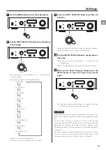
*PCM D-FILTER
> OFF
OFF
The digital filter is disabled.
FIR SHARP
An FIR filter with a steep roll-off is used to sharply cut signals out-
side the audio band.
FIR SLOW
An FIR filter with a slow roll-off is used to gently cut signals out-
side the audio band.
SDLY SHARP
A short delay filter with a steep roll-off is used to sharply cut sig-
nals outside the audio band.
SDLY SLOW
A short delay filter with a slow roll-off is used to gently cut signals
outside the audio band.
o
When receiving signals at 352.8 kHz or 384 kHz, the digital filter
will be disabled during playback regardless of this setting.
DSD digital filter
Use to set the digital filter when receiving DSD format signals.
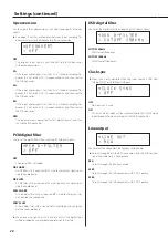
*DSD D-FILTER
> CUTOFF 150kHz
CUTOFF 50kHz
50kHz cutoff frequency
CUTOFF 150kHz
150kHz cutoff frequency
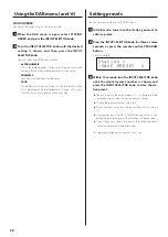
Clock sync
o
Clock sync is only possible when the input source is USB (rear
USB port), NET or USBf (front USB port).
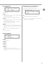
*CLOCK SYNC
> OFF
OFF
No clock sync is used.
ON
This unit’s master clock will be synchronized to the 10MHz clock
input through the clock sync input (10MHz IN) connector.
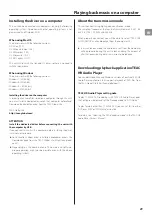
Line output
*LINE OUT
> RCA
Use to select the connectors that output analog audio.
o
Output through both the RCA connectors and the XLR connec-
tors at the same time is not possible.
RCA
Output through the RCA connectors.
XLR2
Output through the XLR connectors with 2: HOT polarity.
XLR3
Output through the XLR connectors with 3: HOT polarity.
Settings (continued)
Summary of Contents for NT-503DAB
Page 99: ...99...

