background image

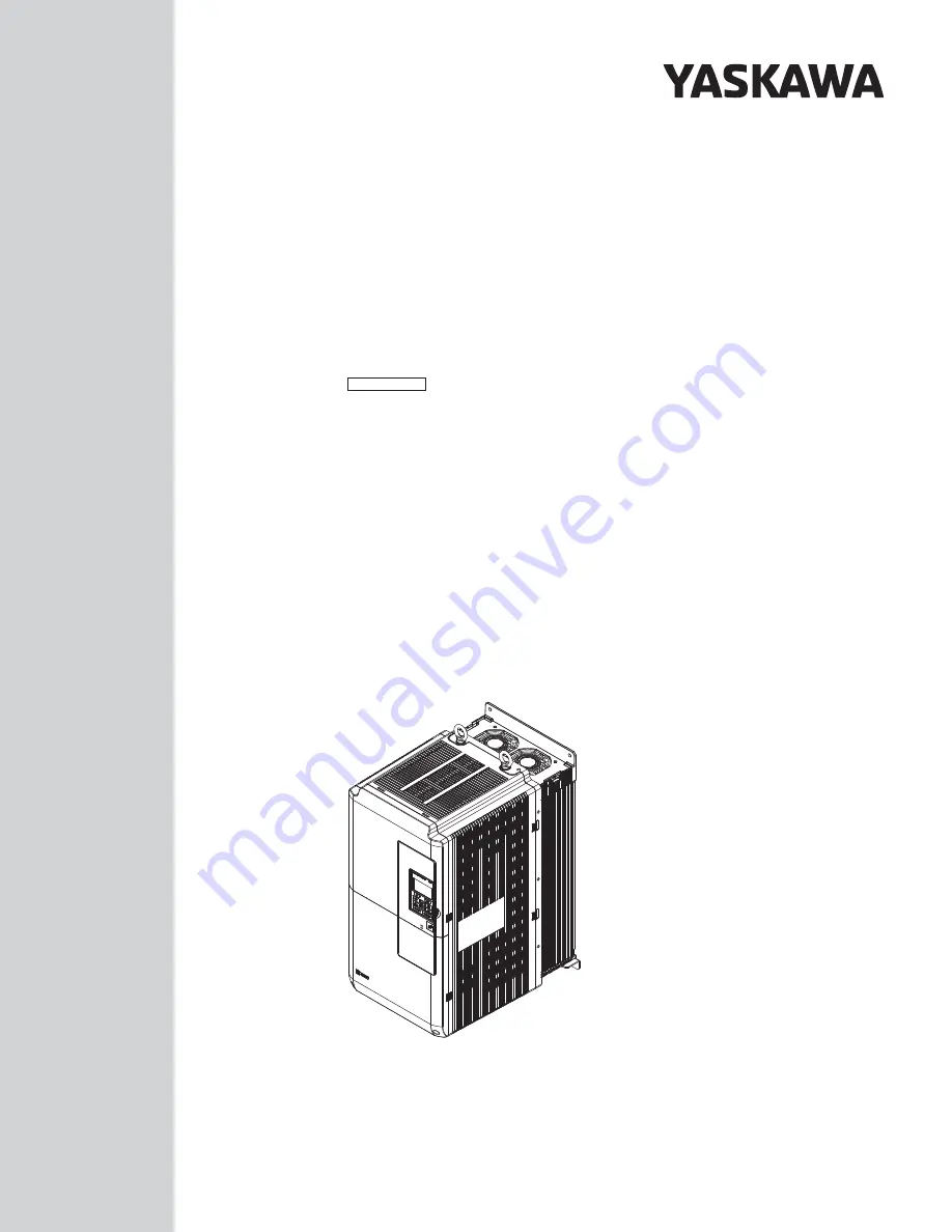
U1000 Industrial MATRIX Drive

Low Harmonic Regenerative Drive for Industrial Applications

Quick Start Guide

MANUAL NO.   TOEP C710636 04D

To properly use the product, read this manual thoroughly and retain 
for easy reference, inspection, and maintenance. Ensure the end user 
receives this manual.

Type: CIMR-UU
Models: 200 V Class: 7.5 to 75 kW (10 to 100 HP ND)

400 V Class: 5.5 to 580 kW (7.5 to 775 HP ND)

Summary of Contents for U1000 iQpump Drive

Page 1: ...Start Guide MANUAL NO TOEP C710636 04D To properly use the product read this manual thoroughly and retain for easy reference inspection and maintenance Ensure the end user receives this manual Type CI...

Page 2: ...patent liability is assumed with respect to the use of the information contained herein Moreover because Yaskawa is constantly striving to improve its high quality products the information contained i...

Page 3: ...INSTALLATION 18 i 4 ELECTRICAL INSTALLATION 25 i 5 START UP PROGRAMMING AND OPERATION 60 i 6 TROUBLESHOOTING 84 i 7 DRIVE SPECIFICATIONS 93 i 8 PARAMETER TABLE 95 i 9 STANDARDS COMPLIANCE 98 i YASKAWA...

Page 4: ...ic settings and trial operation The most recent version of this manual is available for download on our documentation website www yaskawa com U1000 Industrial MATRIX Drive Technical Manual This manual...

Page 5: ...n the control circuit DC voltage is below 50 Vdc To prevent electric shock wait for at least the time specified on the warning label once all indicators are OFF measure for unsafe voltages to confirm...

Page 6: ...C EN 60755 Fire Hazard Do not use an improper voltage source Failure to comply could result in death or serious injury by fire Verify that the rated voltage of the drive matches the voltage of the inc...

Page 7: ...rrent Make sure that the motor rated current is less than the rated output current for the drive When 2 Seconds is Required for Momentary Power Loss Ride Thru Time Use the units listed below when cont...

Page 8: ...ting for the drive determines the starting and accelerating characteristics of the motor Expect lower torque than when running from line power To achieve a higher starting torque use a larger drive or...

Page 9: ...trical Shock Hazard Capacitors in the drive do not immediately discharge after shutting off the power Wait for at least the amount of time specified on the drive before touching any components after s...

Page 10: ...losed Loop Vector control can help reduce motor oscillation Take particular caution when adding a variable speed drive to an application running a motor from line power at a constant speed If resonanc...

Page 11: ...ard Geared Motor Make sure that the gear and the lubricant are rated for the desired speed range to avoid gear damage when operating at low speeds or very high speeds Consult with the manufacturer for...

Page 12: ...ay directly affect or threaten human lives or health Customers who intend to use the product described in this manual for devices or systems relating to transportation health care space aviation atomi...

Page 13: ...TION 2 1 Kurosaki shiroishi Yahatanishi Ku Kitakyushu 806 0004 Japan MADE IN JAPAN AC3PH 380 500V 50 60Hz 10A 8 7A AC3PH 0 475V 0 400Hz 11A 9 6A 20 kg 6W3050 2 100 J0065F575310100 E131457 PASS MODEL C...

Page 14: ...INPUT OUTPUT MASS O N S N FILE NO IP00 REV A A Normal Duty amps Heavy Duty amps B Software version C Address 1 D Enclosure type E Serial number F Lot number G Output specifications H Input specificati...

Page 15: ...S MODEL C C EUJ711800 U INPUT OUTPUT MASS O N S N FILE NO IP00 A Model number B Input specifications C Output specifications D Lot number E Serial number F Address 1 G Enclosure type Figure i 5 Harmon...

Page 16: ...avy Duty HD C6 01 0 Drive Model Reference Motor Capacity kW HP Rated Output Current A Drive Model Reference Motor Capacity kW HP Rated Output Current A 2o0028 7 5 10 28 2o0028 5 5 7 5 22 2o0042 11 15...

Page 17: ...45 60 77 4o0124 75 100 124 4o0124 55 75 96 4o0156 90 125 156 4o0156 75 100 124 4o0180 110 150 180 4o0180 90 125 156 4o0216 132 175 216 4o0216 110 150 180 4o0240 150 200 240 4o0240 132 175 216 4o0302...

Page 18: ...F to 104 F Surrounding Area Install the drive in an area free from oil mist and dust metal shavings oil water or other foreign materials radioactive materials combustible materials e g wood harmful g...

Page 19: ...maintain maximum cooling effects NOTICE Avoid placing peripheral devices transformers or other electronics near the harmonic filter module as the noise created can lead to erroneous operation Take pr...

Page 20: ...200 mm 7 87 in minimum D 120 mm 4 72 in minimum E 60 mm 2 36 in minimum F Airflow direction Figure i 9 Correct Drive Model 4o0720 and Harmonic Filter Module Installation Spacing u Instructions on Inst...

Page 21: ...fully closed C Space between drive and washer D Spring washer open Figure i 10 Spring Washer n Horizontal Suspension of Drive Models 2o0154 to 2o0248 4o0156 to 4o0930 and Harmonic Filter Module To ma...

Page 22: ...ilter module is placed correctly Drive Models 2o0154 to 2o0248 and 4o0156 to 4o0414 WARNING Crush Hazard Use an adequate length of wire to ensure a 50 or wider suspension angle as illustrated in Figur...

Page 23: ...stretched tight 3 Lower the drive when ready to install in the enclosure panel Stop lowering the drive when it is near the floor then slowly begin lowering the drive again very slowly until the drive...

Page 24: ...nical Manual SIEP C710636 04 for IP20 NEMA 1 UL Type 1 and IP00 Open Chassis dimensions The U1000 Industrial MATRIX Drive Technical Manual is posted on the Yaskawa website www yaskawa com i 3 Mechanic...

Page 25: ...nction with wiring designed to shut off the power supply upon drive fault make sure the drive does not trigger a fault output during fault restart L5 02 0 default Failure to comply will prevent the au...

Page 26: ...ne main circuit terminal control circuit terminal M3 M4 Multi function relay output Zero Speed 250 Vac max 1 A 30 Vdc max 1 A min 5 Vdc 10 mA M5 M6 Multi function relay output Speed Agree 1 250 Vac ma...

Page 27: ...ely from the main circuit power supply and other power lines 10 The maximum output current capacity for the V and V terminals on the control circuit is 20 mA Never short terminals V V and AC as it can...

Page 28: ...inal M3 M4 Multi function relay output Zero Speed 250 Vac max 1 A 30 Vdc max 1 A min 5 Vdc 10 mA M5 M6 Multi function relay output Speed Agree 1 250 Vac max 1 A 30 Vdc max 1 A min 5 Vdc 10 mA SP SN 14...

Page 29: ...put card DI A3 10 Slide switch S6 design differs based on PCB model number N C N O N C ETC742611 and later ETC742610 N O 11 Wire the fault relay output separately from the main circuit power supply an...

Page 30: ...ply to these terminals u Drive Models 4o0720 to 4o0930 and Harmonic Filter Modules Control power supply Harmonic filter module Control board p1 1 r1 11 4o0720 to 4o0930 n1 1 U T1 W T3 V T2 Bidirection...

Page 31: ...Main Circuit Terminal Functions Voltage Class Three Phase 400 V Class Function Page Drive Model 4o0720 to 4o0930 Terminal Type X Y Z Main circuit power supply input 1 Power supply input terminals tha...

Page 32: ...barriers A A Insulation barrier Figure i 21 Installing Insulation Barriers n Main Circuit Protective Cover Close the protective cover after wiring the main circuit terminals on drive models 2o0028 to...

Page 33: ...s listed in the following tables are Yaskawa recommendations Refer to local codes for proper wire gauge selections n Three Phase 200 V Class Drives Table i 8 Drive Wire Gauge and Torque Specifications...

Page 34: ...U T1 V T2 W T3 35 1 16 to 50 2 6 to 1 0 2P 35 1 10 to 50 2P 8 to 1 0 2P M8 25 4 25 to 35 4 to 1 25 3 10 to 35 8 to 1 M8 8 8 to 10 8 78 1 to 95 5 p1 n1 2 5 14 2 5 to 4 14 to 12 2 5 14 2 5 to 4 14 to 12...

Page 35: ...to 4 14 to 12 M4 1 to 1 4 8 9 to 12 4 4o0014 R L1 S L2 T L3 4 12 2 5 to 10 14 to 8 2 5 14 2 5 to 10 14 to 8 M5 2 3 to 2 7 20 4 to 23 9 U T1 V T2 W T3 4 12 2 5 to 10 14 to 8 2 5 14 2 5 to 10 14 to 8 M5...

Page 36: ...4 to 53 1 U T1 V T2 W T3 25 3 25 4 to 3 25 3 16 to 25 5 to 3 M6 16 6 16 to 25 6 to 3 16 5 16 to 25 5 to 3 M8 8 8 to 10 8 78 1 to 95 5 p1 n1 2 5 14 2 5 to 4 14 to 12 2 5 14 2 5 to 4 14 to 12 M4 1 to 1...

Page 37: ...M12 31 4 to 39 2 278 to 347 p1 n1 2 5 14 2 5 to 4 14 to 12 2 5 14 2 5 to 4 14 to 12 M4 1 2 to 2 0 10 4 to 17 4 4o0302 1 R L1 S L2 T L3 70 2 3 0 2P 50 to 95 2 1 0 to 4 0 2P 70 2P 3 0 2P 50 to 95 2P 1 0...

Page 38: ...to 150 4P 4 0 to 300 4P M12 31 4 to 39 2 278 to 347 X1 Y1 Z1 50 1 0 50 to 70 1 0 to 2 0 35 1 35 to 50 1 to 1 0 M8 5 4 to 6 0 47 8 to 53 0 U T1 V T2 W T3 150 4P 300 4P 120 to 150 4P 250 to 300 4P 120...

Page 39: ...kcmil Wire Range mm2 AWG kcmil Recomm Gauge mm2 AWG kcmil Wire Range mm2 AWG kcmil EUJ71180o o 1 R L1 S L2 T L3 150 4P 300 4P 120 to 150 4P 250 to 300 4P 120 4P 250 4P 95 to 150 4P 4 0 to 300 2P M12...

Page 40: ...U T1 V T2 and W T3 separate from all other leads to reduce possible interference related issues Failure to comply may result in abnormal operation of drive and nearby equipment n Ground Wiring Follow...

Page 41: ...d Forward run Open Stop Photocoupler 24 Vdc 8 mA Refer to Sinking Sourcing Mode for Digital Inputs on page 47 S2 Multi function input 2 Closed Reverse run Open Stop S3 Multi function input 3 External...

Page 42: ...nction Digital Output 1 M1 Multi function digital output During run 30 Vdc 10 mA to 1 A 250 Vac 10 mA to 1 A Minimum load 5 Vdc 10 mA M2 M3 Multi function digital output Zero speed M4 M5 Multi functio...

Page 43: ...e Terminal Ferrule Type Terminal Wire Type Recomm wire size mm2 AWG Applicable wire size mm2 AWG Recomm wire size mm2 AWG Applicable wire size mm2 AWG TB1 TB2 TB3 TB4 FM AC AM P1 P2 PC SC A1 A2 A3 V V...

Page 44: ...d Power Limited Circuits for requirements concerning class 2 power supplies NOTICE Insulate shields with tape or shrink tubing to prevent contact with other signal lines and equipment Improper wiring...

Page 45: ...transfer of information to enable turning on and operating drive models 4o0720 to 4o0930 and the harmonic filter module Note Connect the drive and harmonic filter module before turning on or operatin...

Page 46: ...ations Connector Port CN500 Location n Cable Specifications Table i 16 Module Communications Connector Cable Specifications Cable Length Cable Connector Exterior Cable Example Approximately 5 m 16 4 f...

Page 47: ...P SN External 24 Vdc 10 u Sinking Sourcing Mode Selection for Safe Disable Inputs Use jumper S3 on the terminal board to select between Sink mode Source mode or external power supply for the Safe Disa...

Page 48: ...Terminal Source Mode The high voltage level of the pulse output terminal depends on the load impedance Load Impedance RL k Output Voltage VMP V insulated 1 5 k 5 V 4 k 8 V 10 k 10 V Note The load res...

Page 49: ...10 to 10 Vdc 2 4 to 20 mA 3 0 to 20 mA 0 to 3 2 u Terminal A3 Analog PTC Input Selection Terminal A3 can be configured either as multi function analog input or as PTC input for motor thermal overload...

Page 50: ...ed ON or disabled OFF Refer to Drive Model Number Definition on page 16 for model number definition Note Use a stand alone EMC filter for drive models 4o0477 to 4o0930 DANGER Electrical Shock Hazard D...

Page 51: ...Drives are shipped with the SW screw installed at the OFF position L1 L2 L3 Figure i 34 Symmetrical Grounded Network n EMC Filter Switch Location ON OFF SW A B E G IG R R S S S1 S2 S3 S4 S5 S6 S7 S8...

Page 52: ...Location Drive Models 2E0042 2W0042 2E0054 2W0054 4E0040 to 4E0077 and 4W0040 to 4W0077 ON OFF SW A B A SW ON B Screw OFF Figure i 37 EMC Filter Switch Location Drive Models 2E0104 2W0104 2E0130 2W01...

Page 53: ...4 2E0192 2W0192 4E0156 4W0156 4E0180 and 4W0180 B A B A A SW ON B Screw OFF Figure i 39 EMC Filter Switch Location Drive Models 2E0248 2W0248 4EU0216 4W0216 4E0240 and 4W0240 i 4 Electrical Installati...

Page 54: ...es not provide power to the main circuit of the drive It is possible to read fault and parameter data in the drive via the operator or network communications when the drive switches to the 24 V Contro...

Page 55: ...43 24 V Control Power Supply Unit Location Models 2P0104 2W0104 2P0130 2W0130 4P0096 4W0096 4P0124 and 4W0124 A A Power Supply Terminal Block TB1 Figure i 44 24 V Control Power Supply Unit Location Mo...

Page 56: ...24 0 and FE terminals as shown in Figure i 47 then tighten the terminal screws to hold wiring in place Refer to Table i 28 to confirm that the proper tightening torque is applied to each terminal Tak...

Page 57: ...licable Gauges mm2 AWG Recomm Gauge mm2 AWG Applicable Gauges mm2 AWG 24 0 FE M2 0 22 to 0 25 1 95 to 2 21 0 75 18 AWG Stranded wire 0 25 to 1 0 24 to 17 AWG Solid wire 0 25 to 1 5 24 to 16 AWG 0 5 20...

Page 58: ...match the drive output specifications 13 7 Verify that the drive is properly sized to run the motor 8 Power supply voltage of models 4o0477 to 4o0930 should not exceed 480 V when connecting with recom...

Page 59: ...circuit wiring mistakes between the harmonic filter module and drive models 4o0720 to 4o0930 31 Control Circuit Wiring 24 Use twisted pair line for all drive control circuit wiring 44 25 Ground the sh...

Page 60: ...ay the previous item selects parameter numbers and decrements setting values 7 STOP STOP Key 1 Stops drive operation 8 ENTER Key Enters parameter values and settings Selects a menu item to move betwee...

Page 61: ...the frequency reference is assigned to the MEMOBUS Modbus Communication Inputs of the drive OP Displayed when the frequency reference is assigned to an Option Unit of the drive RP Displayed when the f...

Page 62: ...display Pressing F2 scrolls the cursor to the right RESET Pressing F2 resets the existing drive fault error 1 Displayed when in Frequency Reference Mode 2 Displayed when in Frequency Reference Mode an...

Page 63: ...SEQ RREF RSEQ RREF RSEQ RREF RSEQ RREF YASKAWA U1000 U1000 XX XX XX XXA XXXXXXXXX Initial Display 5 6 Programming Mode 2 Drive Mode 1 Turn the power on RUN LED lit FWD JOG FWD JOG FWD JOG FWD JOG FWD...

Page 64: ...ription Power supply voltage 200 V class Three phase 200 to 240 Vac 50 60 Hz 400 V class Models 4Aoooo and 4Poooo Three phase 380 to 500 Vac 50 60 Hz 400 V class Models 4Eooooand 4Woooo Three phase 38...

Page 65: ...this mode for general variable speed applications that require precise speed control and torque limit Set High Frequency Injection parameter n8 57 to 1 to achieve a speed control range as high as 1 1...

Page 66: ...er the frequency reference No Parameter Name Setting Range Default b1 01 Frequency Reference Selection 1 0 to 4 1 Setting 0 Operator keypad Using this setting the frequency reference can be input by u...

Page 67: ...ion Card This setting requires entering the Run command via the communication option board by plugging a communication option board into the CN5 A port on the control PCB Refer to the option board man...

Page 68: ...n the frequency falls to the E1 09 value The drive will not perform short circuit braking when b2 01 E1 09 0 Hz CLV and CLV PM A1 02 3 7 For these control modes parameter b2 01 sets the starting frequ...

Page 69: ...ed to Coast to Stop Note This function is not available in CLV A1 02 3 or in control modes for PM motors A1 02 5 6 7 Motor coasts DC Injection Braking with the current set in b2 02 Run command Output...

Page 70: ...motor rotation is not appropriate and may cause problems e g air handling units pumps etc No Parameter Name Setting Range Default b1 04 Reverse Operation Selection 0 1 0 Setting 0 Reverse operation en...

Page 71: ...01 C1 02 1 0 C1 03 C1 04 0 1 C1 05 C1 06 1 1 C1 07 C1 08 Figure i 62 shows an operation example for changing accel decel times The example below requires that the stopping method be set for Ramp to s...

Page 72: ...11 Figure i 63 Accel Decel Time Switching Frequency n C6 01 Drive Duty Mode Selection The drive has two different duty modes from which to select based on the load characteristics The drive rated curr...

Page 73: ...ng the Jog reference through the digital input terminals The drive uses the acceleration and deceleration times that have been selected when switching between each frequency reference The Jog frequenc...

Page 74: ...llustrates the multi step speed selection Table i 37 Multi Step Speed Reference and Terminal Switch Combinations Reference Multi Step Speed Reference H1 oo 3 Multi Step Speed Reference 2 H1 oo 4 Multi...

Page 75: ...tting Range Default d2 01 Frequency Reference Upper Limit 0 0 to 110 0 100 0 n d2 02 Frequency Reference Lower Limit Sets the minimum frequency reference as a percentage of the maximum output frequenc...

Page 76: ...aseblock Command 1 Number appearing in parenthesis is the default value after performing a 3 Wire initialization A1 03 3330 n H2 01 to H2 03 Terminal M1 M2 M3 M4 and M5 M6 Function Selection No Parame...

Page 77: ...most effective when running at rated base frequency check the motor nameplate or specifications Continuous operation at less than line power frequency with 100 load can trigger a motor overload fault...

Page 78: ...operating at below the base frequency causes a motor overload fault oL1 The drive fault output closes and the motor coasts to stop Setting 5 Constant Torque PM Motors Constant Torque Range of 1 1500...

Page 79: ...Motor Base Speed with L1 02 set to one minute Motor overload protection operates in the area between a cold start and a hot start Cold start Characteristics of motor protection operation time in resp...

Page 80: ...erent types of Auto Tuning for induction motors and permanent magnet motors The type of Auto Tuning used differs further based on the control mode and other operating conditions Refer to the tables be...

Page 81: ...uto Tuning is executed Increases accuracy for certain functions like torque compensation slip compensation Energy Saving and Speed Search YES YES Stationary Auto Tuning 3 T1 01 5 A motor test report l...

Page 82: ...rly and in the correct state before energizing the drive Failure to comply could result in death or serious injury from moving equipment When programmed for 3 Wire control a momentary closure on termi...

Page 83: ...ence 25 If the control circuit terminals should supply the frequency reference select the correct voltage input signal level 0 to 10 V or 10 to 10 V or the correct current input signal level 4 to 20 m...

Page 84: ...ation was not possible in OLV Control CoF Current Offset Fault Drive starts operation while the current detection circuit failure or the induced voltage remains in the motor coasting and after rapid d...

Page 85: ...terminal S5 External fault at multi function input terminal S5 EF6 External Fault input terminal S6 External fault at multi function input terminal S6 EF7 External Fault input terminal S7 External fa...

Page 86: ...error oFC01 Option Card Fault at Option Port CN5 C Option not properly connected oFC02 Option Card Fault at Option Port CN5 C Same type of option card is currently connected to oFC03 to oFC11 Option C...

Page 87: ...y Circuit Fault Safety Circuit Fault is detected SEr Too Many Speed Search Restarts The number of Speed Search restarts exceeded the value set to b3 19 SoH Snubber Discharge Resistor Overheat SrC Phas...

Page 88: ...ower Supply Undervoltage Detection Level L2 21 200 V Class Approximately 150 Vrms 400 V Class Approximately 300 Vrms bb Baseblock Drive output interrupted as indicated by an external baseblock signal...

Page 89: ...nt LT 1 Cooling Fan Maintenance Time The cooling fan has reached its expected maintenance period and may need to be replaced Note An alarm output H2 oo 10 will only be triggered if both H2 oo 2F and H...

Page 90: ...ions occurred Contactor to suppress inrush current in the drive was opened Low voltage in the control drive input power This alarm outputs only if L2 01 is not 0 and DC bus voltage is under L2 05 u Op...

Page 91: ...o coast to a stop Auto Tuning faults do not trigger a multi function digital output set for fault or alarm output An Endo error on the digital operator display indicates Auto Tuning has successfully c...

Page 92: ...ault restart the drive and reset the fault Press on the digital operator when the error code is displayed LO RE F2 F1 ESC RUN STOP ENTER RESET RESET MODE oC Overcurrent DRV FWD RESET ALM Resetting via...

Page 93: ...OLV PM 1 20 AOLV PM 1 100 Speed Control Accuracy OLV 0 2 25 C 10 C 77 F 50 F 2 CLV 0 02 25 C 10 C 77 F 50 F 2 Speed Response OLV 10 Hz 25 C 10 C 77 F 50 F CLV 250 Hz 25 C 10 C 77 F 50 F Torque Limit P...

Page 94: ...derating Vibration Shock 10 to 20 Hz 9 8 m s2 2o0028 to 2o0248 and 4o0011 to 4o0414 10 to 20 Hz 5 9 m s2 4o0477 to 4o0930 20 to 55 Hz 5 9 m s2 2o0028 to 2o0081 and 4o0011 to 4o0077 20 to 55 Hz 2 0 m...

Page 95: ...0 kHz 2 6 0 kHz 3 8 0 kHz 4 10 0 kHz F User defined determined by C6 03 to C6 05 Default setting value is determined by A1 02 Control Method Selection C6 01 Drive Duty Selection and o2 04 Drive Model...

Page 96: ...input value selected in H3 10 when 0 V 0 or 4 mA is input at terminal A2 No Name Description H3 13 Analog Input Filter Time Constant Sets a primary delay filter time constant for terminals A1 A2 and A...

Page 97: ...Disabled Drive trips on Uv1 fault when power is lost 1 Recover withinthetimesetinL2 02 Uv1 is detected if power loss L2 02 2 Recover as long as CPU has power Uv1 is not detected L3 04 Stall Prevention...

Page 98: ...h the Low Voltage Directive be sure to meet the following conditions when combining this drive with other devices n Area of Use Do not use drives in areas with pollution higher than degree 2 and overv...

Page 99: ...standards and local safety regulations WARNING Electrical Shock Hazard Because the leakage current exceeds 3 5 mA in models 4o0302 and larger IEC EN 61800 5 1 states that either the power supply must...

Page 100: ...lso comply with EMC guidelines Refer to EMC Filters on page 102 for EMC filter installation 1 Install an EMC filter to the input side specified by Yaskawa for compliance with European standards 2 Plac...

Page 101: ...Wiring Diagram for EMC Models 4o0477 and 4o0590 ELCB MCCB EMC filter Harmonic filter module Three phase power supply Motor Ground shielded line main circuit terminal control circuit terminal Drive R L...

Page 102: ...60 235 240 Figure i 77 4o0590 B84143B1000S080 1000 18 5 410 140 260 235 240 Figure i 77 4o0720 B84143B1600S080 1600 24 5 490 140 260 235 240 Figure i 78 4o0900 B84143B1600S080 1600 24 5 490 140 260 23...

Page 103: ...nce with UL standard UL508C and complies with UL requirements The conditions described below must be met to maintain compliance when using this drive in combination with other equipment n Conditions o...

Page 104: ...052 to 4o0930 Use only the tools recommended by the terminal manufacturer for crimping Yaskawa recommends UL Listed crimp terminals made by JST and Tokyo DIP or equivalent for the insulation cap Table...

Page 105: ...7 4 0 R100 10 YF 1 TD 324 TP 100 100 051 269 2o0192 3 M10 R22 10 YA 5 AD 953 TP 022 100 061 113 2 R38 10 AD 954 TP 038 100 061 114 1 2 1 0 R60 10 AD 955 TP 060 100 051 266 2 0 70 10 YF 1 YET 300 1 TD...

Page 106: ...5 AD 952 TP 014 100 051 261 4 2 R22 6 AD 953 TP 022 100 051 262 3 4o0077 4 M6 R22 6 YA 5 AD 953 TP 022 100 051 262 3 2 4o0096 8 M8 R8 8 YA 4 AD 901 TP 008 100 601 111 6 R14 8 AD 902 TP 014 100 054 035...

Page 107: ...60 100 051 266 2 0 70 10 TD 322 TD 311 TP 080 100 064 251 3 0 80 10 TD 323 TD 312 100 051 267 4 0 R100 10 TD 324 TD 312 TP 100 100 051 269 4o0302 1 0 M10 R60 10 YF 1 YET 300 1 TD 321 TD 311 TP 060 100...

Page 108: ...311 TP 060 100 066 160 2 0 70 12 TD 322 TD 311 TP 080 100 054 036 4 0 R100 12 TD 324 TD 312 TP 100 100 051 270 250 R150 12 TD 325 TD 313 TP 150 100 051 273 300 2 R150 12 TP 150 100 051 273 4o0900 1 0...

Page 109: ...Vac UL approved vinyl sheathed insulation n Low Voltage Wiring for Control Circuit Terminals Wire low voltage wires with NEC Class 1 circuit conductors Refer to national state or local codes for wirin...

Page 110: ...with a speed range of 1 100 Selects protection characteristics for a motor capable of cooling itself at any speed including zero speed externally cooled motor The motor overload detection level oL1 i...

Page 111: ...ontinued and an oH3 alarm is displayed on the digital operator n L1 04 Motor Overheat Fault Operation Selection PTC input Sets the drive operation when the PTC input signal reaches the motor overheat...

Page 112: ...CSA C22 2 No 14 13 Figure i 81 CSA Mark u Safe Disable Input Function This section explains the Safe Disable function Contact Yaskawa if more information is required n Safety Standards The TUV mark i...

Page 113: ...otor will move when an external gravitational force in the vertical axis is applied even if the Safe Disable function is in operation Failure to comply may result in serious injury or death DANGER Sud...

Page 114: ...trates the Safe Disable input operation H1 H2 Input Drive Output ON Safe Disable off Normal operation OFF Safe Disable activated Safe Torque Off Run Command Run Stop Baseblock Not Safe Output Frequenc...

Page 115: ...e instruction manual of the safety device for details on this function Digital Operator Display When both Safe Disable inputs are open Hbb will flash in the digital operator display If one Safe Disabl...

Page 116: ...Harmonic Filter Module EUJ71180o o EUJ71181 o o EUJ71182o o Standards Compliance Addition EMC Guidelines Compliance for models 4o0477 to 4o0930 CSA Standards Compliance Back Cover Revision Address Fo...

Page 117: ......

Page 118: ...2 017 0099 Fax 66 2 017 0799 http www yaskawa co th YASKAWA ELECTRIC CHINA CO LTD 22F One Corporate Avenue No 222 Hubin Road Shanghai 200021 China Phone 86 21 5385 2200 Fax 86 21 5385 3299 http www y...

Reviews: