409-2908
11
of 32
Rev A
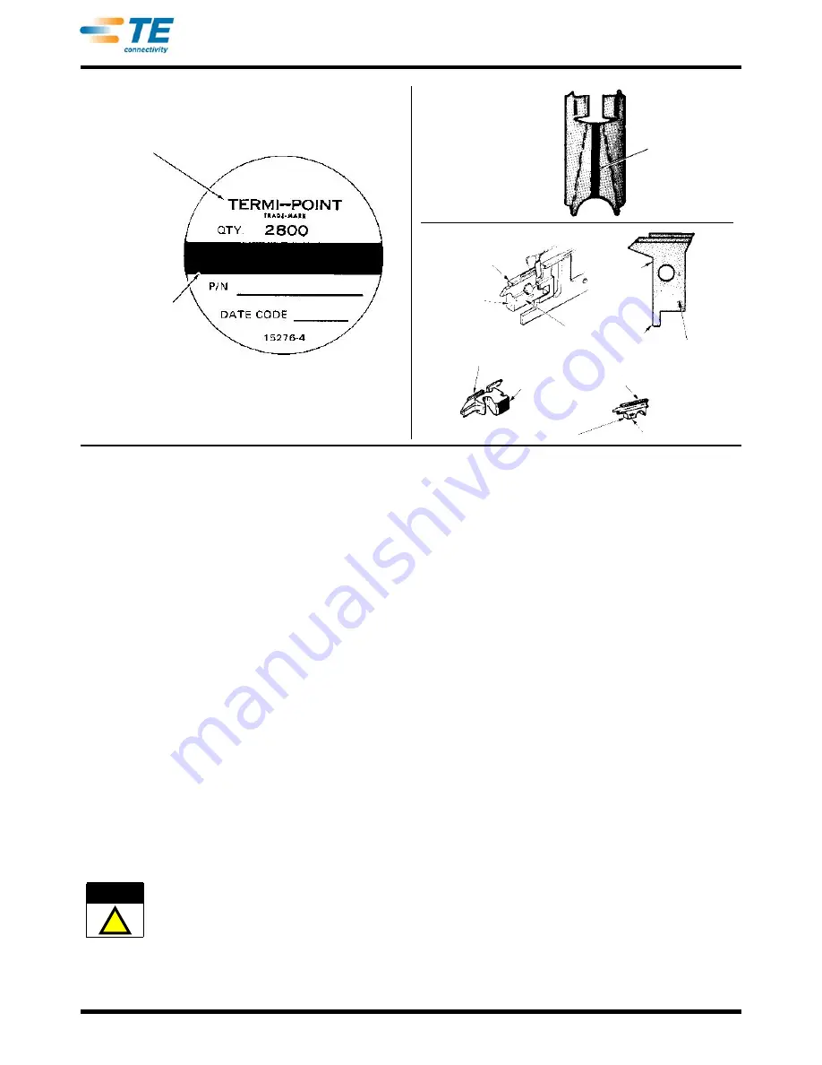
Figure 18
5. REFERENCES
The following instruction sheets provide related information for the TERMI-POINT Air Tools:
•
408-1920 (Quality Control Procedure for TERMI-POINT Clip Applications)
•
408-1933 (TERMI-POINT Pull Test Tool No. 69358 and Test Tip 69544)
•
408-1942 (TERMI-POINT Extraction Tool 69357)
•
408-2019 (Operator’s Quality Check Procedure for TERMI-POINT Clip Application)
•
408-2221 (New Tool Warranty and Exchange Policy for TERMI-POINT Tooling)
•
408-2370 (TERMI-POINT Tool Mandrel Maintenance and Repair)
6. OPERATING INSTRUCTIONS
6.1. Installation of Mandrel
1. Disconnect tool from factory air supply
2. Select correct mandrel for wire size and clips being used. Refer to Section 3. Make sure the color code data
for the mandrel, clips, and wire size are compatible.
3. Remove tooling foot by removing two screws. See Figure 19.
4. Remove mandrel holding screw.
5. Open both post pickups and insert mandrel; align hole in mandrel with mandrel holding screw hole, as
shown in Figure 19.
Use care not to push against stripping ear area of mandrel so as not to damage cutting edge of mandrel.
6. Release post pickups and insert and tighten mandrel holding shoulder screw.
7. Re-install tooling foot with two screws.
Clip Identification
Label
Color .031 x .062 in.
Clips Only
Color Code
Typical Clip 330495-[ ]
Series Only
(.031 x .062 in.)
Air Tool Mandrel
(.031 x .062 in.)
Color Code
Part Number
Color Code
Part Number
Mandrel
for Air Tool
59865-[ ]
and
59928-[ ]
Color Coded
Part Number
Manual Tool
Mandrel
(.031 x .062 in.)
Part Number
Color Code
Mandrel Insert
(.022 x .036 in.)
CAUTION
!


