EPP-1988-INT-7/13 4/20
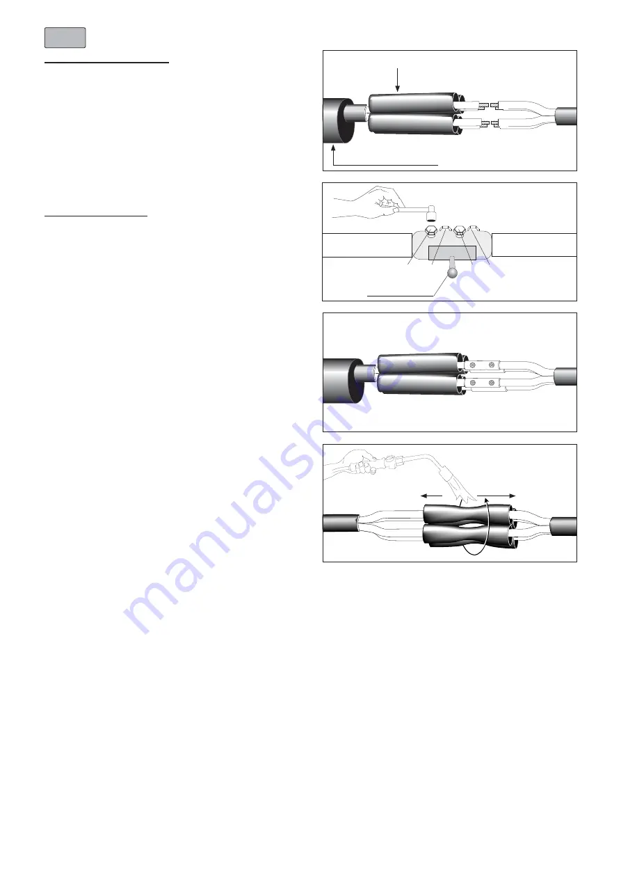
Position the inner insulation tubes centrally over the
connector area.
Shrink down the inner insualtion tubes, starting in the center
of the connectors, working towars the ends.
Before shaping the cores and laying them to each other,
allow the inner insulation sleeves to cool down.
5
Completion of the joint
Position the outer sealing sleeve over one of the cleaned
cable ends. Position the inner insulation tubes over the
long core ends.
Note:
Use only mechanical connectors supplied with the joint kit.
The screws of all connectors have to point to the outside, not
in the direction to the other cores.
The screws of the connector have to touch the outer wide
side of sector shaped conductors. If required sector shaped
cores have to be turned to the outside.
Conductor connection:
Wire brush the aluminium conductors. Hand tighten the
shear bolts so that the connector stays in place. For
connectors using more than one shear bolt per side, tighten
the bolts alternately and shear them off starting with the
outer bolts.
(see also sequence shown in the drawing).
Note:
When a cordless impact wrench is in use the tightening
intervals should be in the range of 2 seconds.
Avoid core bending on smaller cross sections by using a
support tool.
Note:
The sheared-off bolts should protrude the connector for not
more than 4 mm.
Clean and degrease the connector area and the core
insulation.
2
Inner insulation tubes
Outer sealing sleeve
4
3
Support tool
1
2
4
3
EN
NOTE -
When continuing, choose OPTION:
• OPTION
S:
Installation using
Outer Sealing Sleeve
-
see steps
6 S - 7 S
.
• OPTION
W:
Installation using
Wraparound Joint Sleeve
- see steps
6 W - 8 W
.


