


408-2681
2 of 5
Rev C
Figure 3
5. Crimp the contact by squeezing the tool handles.
Then tighten screws of the hold-down device and
contact locator. If the contact crimp is straight and
the wire barrel has not been damaged, the tool is
ready to use.
If the tool has been preset for wire size 10 AWG -
the smallest wire size-no further adjustment is
necessary, even though wire size 8 or 6 AWG is to
be terminated; the setting for wire size 10 will also
accommodate wire size 8 or 6. However, if the anvil
die is not set for wire size 10 and wire size 8 or 6 is
desired, then the anvil die should be set to the
appropriate wire size of either 8 or 6.
6. If the wire size marking is positioned for a wire
size other than desired, depress the anvil die
spring-loaded indexing pin and rotate the anvil die
until the desired size appears. Then release the
indexing pin and allow locator pin to snap into the
hole which locks the anvil die in place for the
desired size.
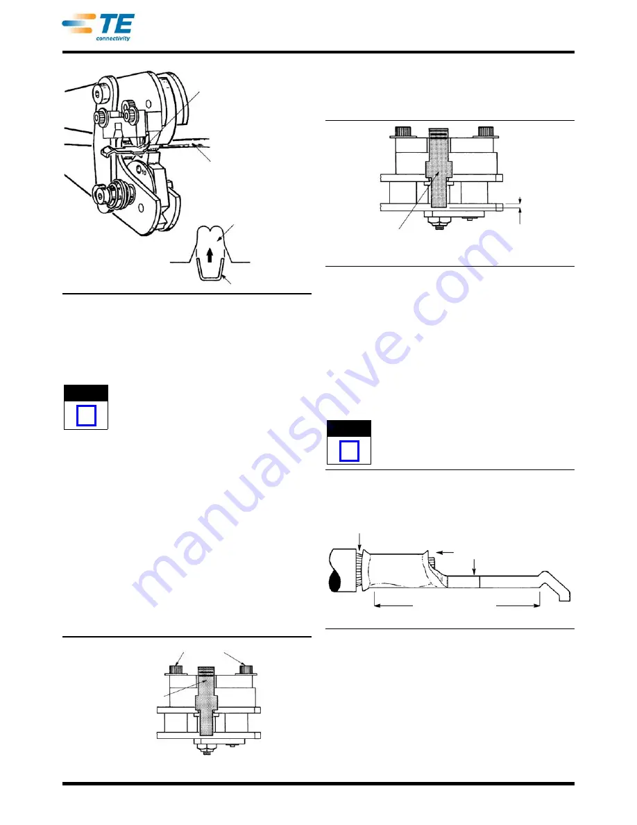
7. Open the tool head, and position the contact in
the nest, locating the outer end of the wire barrel
(wire-entry end) so that it extends from the nest
area between 0.76 to1.02 mm [.030 to .040 in.] as
shown in Figure 4.
Figure 4
8. Close tool head just enough to retain the contact;
then insert the wire into the wire barrel, making sure
the wire does not extend beyond the wire barrel.
See Figure 5.
Figure 5
9. Slowly squeeze the handles, making sure contact
remains aligned properly in the nest. It may be
necessary to open the handles slightly, allowing the
contact to be re-adjusted in the nest. Continue to
squeeze the handles to complete the crimp.
4. CRIMP INSPECTION
Inspected the crimped contact according to Figure 6.
Poorly crimped contacts can be avoided through
careful use of these instructions.
For a detailed inspection requirements, refer to
Application Specification 114-6032.
Figure 6
5. MAINTENANCE AND INSPECTION
5.1. Daily Maintenance
It is recommended that each operator of the tool be
made aware of-and responsible for-the following steps
of daily maintenance:
1. Remove dust, moisture, and other contaminants
with a clean brush, or a soft, lint-free cloth. DO NOT
use objects that could damage the tool.
Wire Conductor Flush
with or Recessed
Slightly in Wire Barrel
Wire Insulation Does
Not Enter Contact
Wire Barrel
Contact Must Retain
Proper Position in
Nest During Entire
Crimping Procedure
Configuration
of Nest
Wire Barrel
NOTE
i
Hold-Down Device and Contact Locator Screws
Torque of Contact
Fits in Slot
Wire Does Not Extend into
Contact Transition Area
Wire Barrel Extends
0.76-1.02 [.030-.040]
from Nest
NOTE
i
Wire Strands Visible Here -
Insulation Must Not Enter
Wire Barrel
Wire Strands Must Not
Extend Beyond this Area
or Above Wire Barrel
Crimp Inspection
Contact Must be
Straight in this Area


