


EXcel4 Controller
Page 22
2.16
Ethernet Communications
If you are connecting the EXcel
4
to an existing network, contact the network
administrator to be allocated a suitable IP address.
Before connecting the Ethernet port to anything, re-position the 5 dip-switches
accordingly. Switch 1 should be ON (up) for IP connection. Switches 2, 3, 4 & 5 provide
RS485 end-of-
line termination. Termination is required when connecting multiple ACU’s
via RS485 from the IP-connected ACU. Only one set of termination switches should be on
for the whole RS485 communications line.
Connect the EXcel
4
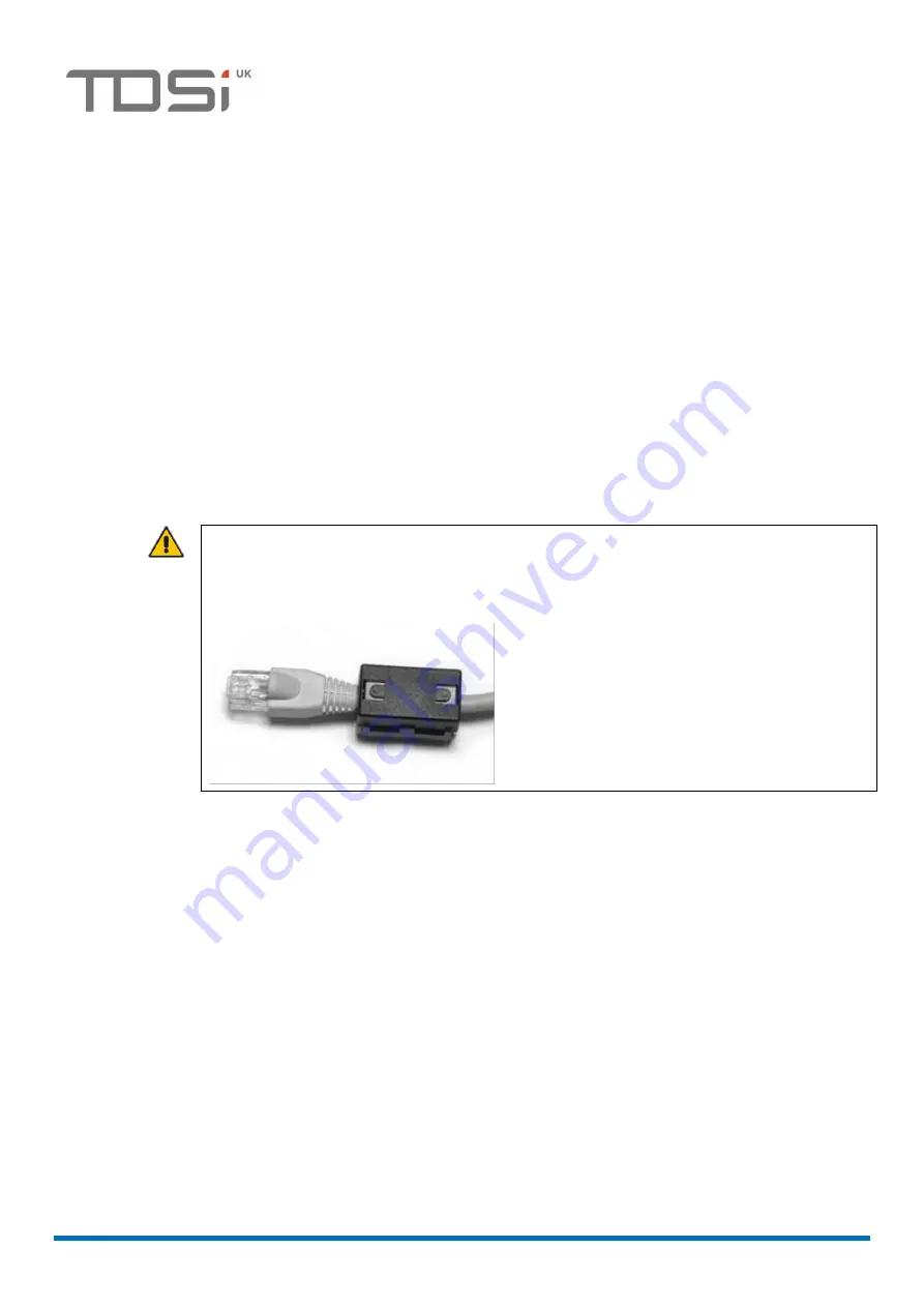
to the network or computer, using a lead with a ferrite sleeve
installed (see picture below). If there is more than one EXcel 4, they can all be
connected at this stage
–
but make a note of the UID number of each unit and its
location to help you identify each unit during setup. If required, to confirm that the
network is connected correctly, you can observe the light inside the Ethernet port: a
steady light means a connection exists but there is no data on the line; a flashing light
indicates data on the line (but not necessarily directed at, or coming from, the port).
CAUTION! If you are connecting the EXcel
4
to a network, the Ethernet patch lead must
have a ferrite sleeve installed at the end that is plugged into the EXcel
4
. The ferrite
sleeve is supplied with the EXcel
4
and must be installed as close as possible to the end
of the lead:


