


45
83503001 Rev G
WARNING
OUTPUT TERMINAL GROUNDING
There is a potential shock hazard at the RS232/RS485 and the IEEE
ports when using power supplies with rated or combined voltage
greater than 400V with the Positive Output of the power supplies
grounded. Do not connect the Positive output to ground when using
the RS232/RS485 or IEEE under the above conditions.
3.10.
Local and Remote Sensing
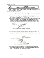
The rear panel J2 sense connector is used to configure the power supply for local or
remote sensing of the Output Voltage. Refer to Fig.3-15 for sense connector
location.3.10.1
3.10.1. Sense Wiring
WARNING
There is a potential shock hazard at the sense connector when using
a power supply with a rated Output Voltage greater than 40V. Local
sense and remote sense wires should have a minimum insulation
rating equivalent or greater than the maximum Output Voltage of the
power supply. Ensure that the connections at the load end are
shielded to prevent accidental contact with hazardous voltages.
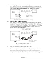
3.10.2. Local sensing
The power supply is shipped with the rear panel J2 sense connector wired for local
sensing of the Output Voltage. See Table 3-4 for J2 terminals assignment. With local
sensing, the Output Voltage regulation is made at the output terminals. This method
does not compensate for voltage drop on the load wires, therefore it is recommended
only for low load current applications or where the load regulation is less critical.
J2
OFF
ON
SW1
Fig. 3-15: Sense Connector Location
Terminal
Function
J2-1
Remote positive sense (+S)
J2-2
Local positive sense. Connected internally to the positive output terminal (+LS).
J2-3
Not connected (NC)
J2-4
Local negative sense. Connected internally to the negative output terminal (-LS).
J2-5
Remote negative sense (-S).
Table 3-4: J2 Terminals


