


JM50 Rapid Roller Door Operator
5
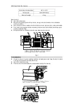
Fig.3
Make sure the door shaft which out of the door operator about 160mm.
To install the bracket on the fix board, determine the location, mark and drill the 2 holes
(
Ø
11).
Fix the bracket on the operator with 4 screws M8x16. Make sure that the bracket is plumb
and lever. See Fig.2
The bracket installation should meet the specifications as shown in figure 3
Slot the door operator with bracket onto the door shaft (ensure correct position of the key)
and screw onto the fix board with 2 bolts M10×25 and 2 nuts M10.
Slot the encoder onto the door shaft and push it close to the door operator and screw onto
the door operator with screw M8×16.
Tight the screw on the encoder, make sure the encoder rotates with the shaft
simultaneously.
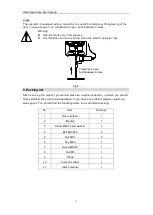
4. Wiring
Before carry out any wiring work, it is essential to disconnect the control unit from the mains
supply.
Motor
Open the wiring terminal block cover, connect motor as shown in Fig.4.
Factory preset:
△
Wiring (PLC Input single-phase 220V, Output three-phase 220V)
Y Wiring (PLC Input three-phase 380V, Output three-phase 380V)
Fig.4
Electromagnet brake
Connect power wires 220V (terminal block D, N1 of control box) to yellow wires of rectifier.
Connect two wires of electromagnet to black wires.
The non-excitation brake is adjust be
Fig.5
Manual operation
V1
U1
W1
U2
W2
V2
W
V
U
V1
U1
W1
U2
W2
V2
W
V
U
~380V
~220V
Y Wiring
Wiring
(Factory preset)
AC220V
Input
DC99V
Output
Yellow
Black
Black
D
N1
Control
Board
Yellow


