2800 LAURA LANE • MIDDLETON, WI 53562 • (800) 288-9383 • FAX (608) 836-9044 • www.tcsbasys.com
5
Operation
uNoCCuPIEd SETBACK
The SZ1143b operates in either an occupied or unoc-
cupied mode. During the occupied mode, the occupied
deadband will be used. During the unoccupied mode,
the unoccupied deadband will be used.
Digital Input 1 is used to set the occupied and unoccu-
pied mode of the SZ1143b. If the connection from "DI1"
to "COM" (ground) is "Open", the SZ1143b functions in
Occupied Mode. If the connection from "DI1" to "COM"
(ground) is "Closed", or "Shorted", the SZ1143b func-
tions in Unoccupied Mode.
ANALog INPuT
The SZ1143b's 4 to 20mA inputs utilize differntial input
circuits. The +P terminal is a DC power supply for 2-wire
(loop powered) 4 to 20mA inputs. To connect a 2-wire
4 to 20mA transmitter (temperature, pressure, humidity)
to the SZ1143b, connect the +P terminal of the SZ1143b
to the (+) terminal of the transmitter and connect the IN1
(or IN2) terminal of the SZ1143b to the (-) terminal of the
transmitter. Leave the respective RTN1 or RTN2 jumper
installed. This jumper connects terminal RTN1 or RTN2
to the GND or C terminal and completes the circuit.
If connecting a self powered 4 to 20mA signal to the
SZ1143b, connect the (+) signal to the IN1 (or IN2) ter-
minal of the SZ1143b and the (-) signal or return to the
RTN1 (or RTN2) terminal of the SZ1143b. Remove the
respective RTN1 or RTN2 jumper.
If sending one signal to two SZ1143b units, for example
outdoor air temperature, Connect the +P terminal one
of the SZ1143b’s to the (+) terminal of the transmitter.
Connect the (-) terminal of the transmitter to the IN1
(or IN2) terminal of the second SZ1143b. Connect the
RTN1 (or RTN2) terminal of the second SZ1143b to
the IN1 (or IN2) terminal of the first SZ1143b. Remove
the RTN1 (or RTN2) jumper from the second SZ1143b.
Refer to “Sharing analog inputs on an SZ1143b”
Application note for more detail.
hIgh / LoW CoNTRoL
The analog input and analog outputs can be setup to
perform High/Low signal selection. This is done by
selecting "YES" in programming step # 4. When using
the SZ1143b as a High/Low signal selector no other
modes of operation work.
STAGE 1
OFFSET:
0%
34.
STAGE 1
DIFF:
2%
35.
STAGE 2
OFFSET:
2%
36.
STAGE 2
DIFF:
2%
37.
DI2 USED FOR:
MONITOR
38.
DO2 SETPOINT
USED: SETPOINT 1
39.
DO2 PRIMARY
SETPOINT2:
75
40.
DO2 UNOCCUPIED
DEADBAND2:
5%
41.
SET ACCCESS
CODE:
248
42.
AI1
0
AI2
0
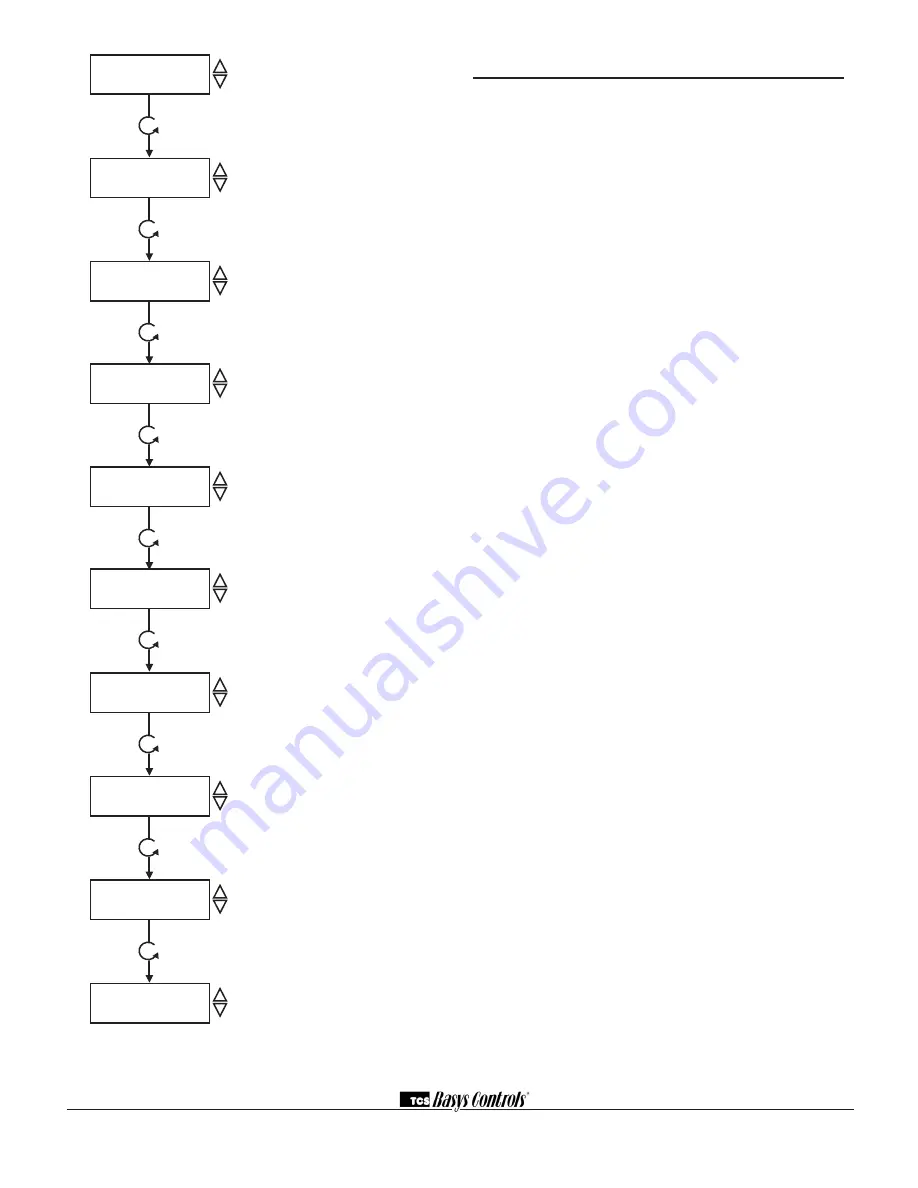
digital output 1 offset Screen.
Enter
an offset value for digital output one. A
first stage is normally set to 0 offset. The
offset is a percentage of input span.
digitaI output 1 differential Screen.
Enter a differential value for digital output
one. The differential is a percentage of
input span.
digital output 2 offset Screen.
Enter
an offset value for digital output two. The
offset is a percentage of input span.
digital output 2 differential Screen.
Enter a differential value for digital output
one. The differential is a percentage of
input span.
digitaI Input 2 Mode Screen.
Choose
DI2 as Monitor or Aquastat. Aquastat
reverses the action of the analog output.
do2 Setpoint Mode Screen.
Choose
whether DO2 will be controlled by
the "Main" Setpoint1 or from its own
Setpoint2.
do2 Setpoint Screen.
Enter a setpoint
value for control. (This screen only
appears if the DO2 Setpoint Mode is
chosen to be Setpoint2.)
unoccupied deadband Screen.
Enter
an unoccupied deadband for DO2. This
is a number from 0 to 100% of input
span. (This screen only appears if the
DO2 Setpoint Mode is chosen to be
Setpoint2.)
Access Code Screen.
Enter an access
(0-255) code that will be used to enter
the programming mode. The default is
248.
Main Monitoring Screen.


