R
2800 LAURA LANE • MIDDLETON, WI 53562 • (800) 288-9383 • FAX (608) 836-9044 • www.tcsbasys.com
3
Programming
The SZ1000 may be programmed through the display
and keypad, or with a PC.
If programming with a PC, the following must be set
through the keypad prior to programming:
• Address (step #2)
• Baud rate (step #3)
For more information on programming through the PC,
consult your TCS software manual.
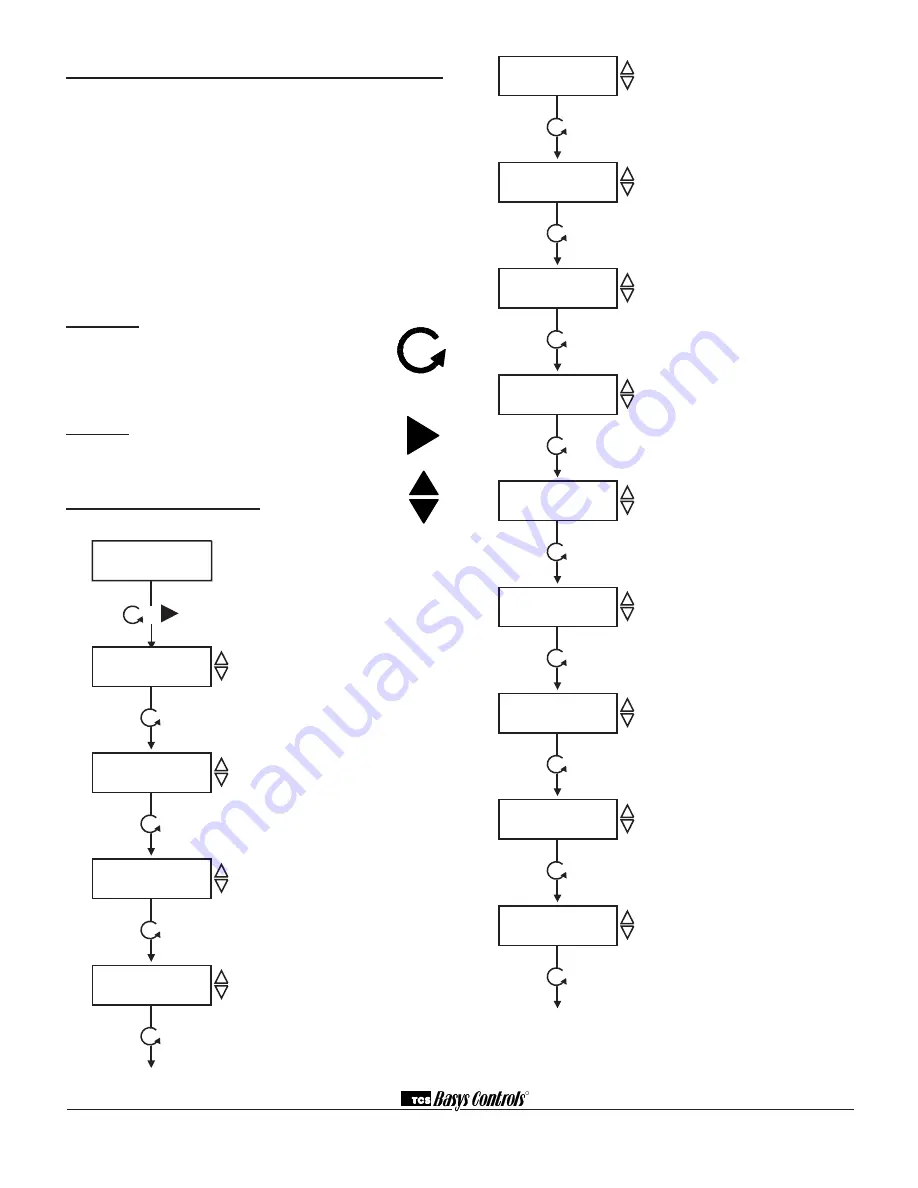
Programming through the KeyPad
To access the programming screens, press both the
“Scroll” and “Next” keys simultaneously.
scroll Key
- The "Scroll" key is also used to
save any changes to the "current" screen and
advance to the next screen while program-
ming. The "Scroll" key is used to enter the
Programming Mode when pressed with the
"Next" key.
next Key
- Used to enter Programming Mode
when pressed with the “Scroll” key. Also used to
exit programming without saving changes to the
current screen.
increment/decrement Keys
- Used to select the
desired value.
METER 1 TYPE:
ELEC 1 PH
meter 1 type screen.
Select either ELEC 1 PH, BTU, WATER,
GAS, ELEC 3 PH. This screen does not
show if NO was selected in step 4.
METER 1 CT VALUE:
0.60
meter 1 Ct Value screen.
Enter the value for the CT wired to Meter
input 1 (this value should be provided on
the CT or Energy Meter from the Utility).
This screen does not show if NO was
selected in step 4 or if BTU, Water or Gas
was selected in step 5.
METER 1 P/REV:
4.00
meter 1 Pulse Per revoltion screen.
Enter the value for the Pulses per revolt-
ion for meter input 1, (this value should
be provided on the CT or Energy Meter
from the Utility). This screen does not
show if NO was selected in step 4.
METER 1 CONSTANT:
1.00
meter 1 Constant screen.
Enter the value for the constant for meter
input 1 (this value is provided from utility
company). This screen does not show if
NO was selected in step 4.
METER 1 CU FT/P:
5.00
meter 1 Cubic Feet Per Pulse screen.
Enter the value for Cubic Feet per pulse.
This only applies to
water
,
gas
and
Btu
(this value is provided from utility
company). This screen does not show if
NO was selected in step 4.
METER 1 MULT:
1.00
meter 1 multiplier screen.
Enter the multiplier for meter input 1 (this
value is provided from utility company).
This screen does not show if NO was
selected in step 4.
SETUP METER 2:
NO
meter 2 setup screen.
Select either Yes or No to program Meter
input two. If no is selected skip to step 18.
METER 2 TYPE:
ELEC 1 PH
meter 2 type screen.
Select either ELEC 1 PH, BTU, WATER,
GAS, ELEC 3 PH. This screen does not
show if NO was selected in step 11.
METER 2 CT VALUE:
0.60
meter 2 Ct Value screen.
Enter the value for the CT wired to Meter
input 2 (this value should be provided on
the CT or Energy Meter from the Utility).
This screen does not show if NO was
selected in step 11 or if BTU, Water or
Gas was selected in step 12.
5.
6.
7.
8.
9.
10.
11.
12.
13.
ENTER ACCESS
CODE: 000
access Code entry screen.
Enter the access code. If the wrong
access code is entered, the program
reverts to the main screen. 248 is the
default access code.
SET ADDRESS:
100
Controller address screen.
If using a PC to access the SE1000, set
a unique address from 0 to 255, exclud-
ing 248.
SET BAUD RATE:
9.6K
Communication Baud rate screen.
Is using a PC to access SE1000, all con-
trollers on a network must be set to the
same baud rate. Choose between 2.4K,
4.8K, 9.6K and 19.2K.
SETUP METER 1:
NO
setup meter 1 screen.
Select either Yes or No to program Meter
input one. If no is selected skip to step 11.
1.
2.
3.
4.
Meter 1 Demand
0.00 kW
+
main monitoring screen


