background image


L2E Repair Document 


TCL

 Communication Ltd.


Rev. 

VFD 700 Level 2 Enhance Repair Document 

Page 

1.0 

72/77 

All rights reserved. Transfer, copy, use or communication of this file is prohibited without authorization. 


APPENDIX 1 Packaging Requirements


1. 

Any L3 PCBA which has appearance like below cases is not acceptable. 


  1) The PCBA which 

shielding cover is rusty or distortion, copper peel off


  2)

 Smudge

 on PCBA, such as soldering flux, rudimental glue, handwriting, burn, scratch and so on ; 


× 

× 

× 

× 

Summary of Contents for VFD 700

Page 1: ...t Page 1 0 1 77 All rights reserved Transfer copy use or communication of this file is prohibited without authorization SHINE PLUS VF VFD 700 Note this manual is non contractual and TCL Communication Ltd can modify it without prior notice on the characteristics of described equipments ...

Page 2: ...evel 2 Enhance Repair Document Page 1 0 2 77 All rights reserved Transfer copy use or communication of this file is prohibited without authorization 1 0 2016 4 15 Draft creation Peter ye Rev Date Modification description Prepared By Checked By Approved By ...

Page 3: ...ad 20 4 1 Equipments requested when download 20 4 2 Install driver 20 4 3 SW download process 21 5 Disassembly and assembly VFD 700 25 5 1 ESD Safety 25 5 2 Disassembly tool 25 5 3 Disassembly process 26 Disassembly Notice 33 5 4 Reassembly Process 34 5 5 Disassembly process evaluation 35 6 Disassembly Complete 36 7 Level 2 repair 39 7 1 power on issue 错误 未定义书签 7 2 Charge issue 错误 未定义书签 7 3 Displa...

Page 4: ...copy use or communication of this file is prohibited without authorization 8 PCBA exchange 50 8 1 Position of L2 enhance components on main PCBA 50 8 2 Trouble shooting for common failures 53 8 3 L2 enhance spare part list 69 9 PCBA exchange 70 10 Other component exchange 70 Function Test 71 APPENDIX 1 Packaging Requirements 72 ...

Page 5: ...r communication of this file is prohibited without authorization 1 Level 2 repair process Reassembly Record in BIG End OK Retest OK OK Start Visual Inspection Warranty Check Pretest Failure confirm SW Upgrade Disassembly L2 Repair Retest Function test PCBA Replace NG NG NG Restore User Information Back up user data L2E Repair Retest OK NG ...

Page 6: ...onfirmation of L1 IMEI sticker check 1 Power on the handset enter 06 2 If the IMEI sticker in the back casing is not lost We should make sure that the IMEI number MUST be the same with the one on the IMEI sticker if not it s out of warranty policy Humidity sensitive label If humidity sensitive label is not good the cell phone will be considered as out of guarantee 1 Liquid was detected by humidity...

Page 7: ...aces 2 Hole diameter 1mm Holes on any surface including the front casing furnished frame battery cover touch Lens keypad 3 Bump Bumps diameter 1mm on any surface including front casing decorate frame battery cover touch Lens keypad etc 4 Scratch Scratches length 3mm on any surface including the front casing decorate frame battery cover touch Lens keypad etc 5 Distortion Bend twisted or crushed on ...

Page 8: ...y 3 Power on the cell phone 4 If the cell phone cannot power on visually check the condition of the battery connector Replace it if necessary 5 If the cell phone asks to input NCK code this means it is SIM locked and can only be worked with dedicated SIM card Use the correct SIM card 6 Enter the phone code if necessary 7 Enter auto test in power off mode 8 Press 2886 in dial screen and then you wi...

Page 9: ...ss to continue TP0 I Please draw on the yellow area according to instructions II Press Pass to continue TP1 I Please draw on the yellow area according to instructions II Press Pass to continue TP2 III Please draw on the yellow area according to instructions IV Press Pass to continue LCD MIRE I You will see the LCD display three colors RED GREEN and BLUE if it functions well II Press Pass to contin...

Page 10: ...EL I You will see the LCD displays grey level if it functions well II Press Pass to continue LCD WHITE I You will see the LCD displays white if it functions well II Press Pass to continue KEYPAD I Press the key displayed on the screen The key on the screen will turn grey when you press it if it functions well II Press Pass to continue BACKLIGHT I The screen backlight will be flashing if it functio...

Page 11: ...if it functions well II Press Pass to continue CAMERA LED I Main Camera LED will turn on if it functions well II Press Pass to continue FRONT CAMERA LED I Front Camera LED will turn on if it functions well II Press Pass to continue CHARGER LED I The charge LED will turn on if it functions well II Press Pass to continue AUDIO I You will hear a voice prompt which introduces some emergency call numbe...

Page 12: ...ASS to continue III Make a noise near the SUB MIC you will hear it from the bottom receiver if it functions well IV Press PASS to continue VIBRATOR I You can feel the phone s vibrating if it functions well II Press Pass to continue PROXIMITY I Please shawdow the senor according to instruction and it will say near OK far OK if it functions well II Press Pass to continue ACCESSORY I Insert headset a...

Page 13: ...a noise near the headset mic you will hear it from headset if it functions well VI Press Pass to continue VII You could hear the FM Radio from the headset if it functions well VIII Press Pass to continue IX Remove headset according to the instruction and press Pass to continue X Press Pass to continue CHARGER I Insert USB cable according to instruction and it will say Charger OK Current xxx if it ...

Page 14: ...ue III Put the handset FACE DOWN DOWN LEFT RIGHT and FACE UP according to instruction and then the instruction will disappear if it functions well IV Press Pass to continue Light Sensor I It will show the value of ambient light and the value will change according to the phone s environment Bright or Dark then it will say dark OK bright OK if it functions well II Press Pass to continue SIM CARD I I...

Page 15: ...nctions well II Press Pass to continue BT I Bluetooth will search automatically and it will display device address if it functions well II Press Pass to continue WIFI I It will search for WIFI hot spot and it will display searched result on the screen if it functions well II Press Pass to continue GPS I It will run GPS and search for satellite and then it will display info such as PRN SNR etc on t...

Page 16: ...munication Ltd Rev VFD 700 Level 2 Enhance Repair Document Page 1 0 16 77 All rights reserved Transfer copy use or communication of this file is prohibited without authorization 3 Battery 3 1Battery information 1 Battery picture ...

Page 17: ... 2 Battery feature 3 Battery life The bellowing table shows the nominal battery life respectively in standby and talking mode These typical values are expressed in normal temperature with battery initially full charged and under good ratio coverage Battery range depends on the network characteristics the ambient temperature and particularly on movement Model Element Capacity Battery Li Lithium 296...

Page 18: ...during period of silence 4 Battery charge time For a normally discharged battery which has not been stored for long time the charge time listed as below table Battery type Typical Charge time Soft pack 100 minuets Note If the battery is new charge it before use Battery icon will appear after charging a short time If the battery is deeply discharged battery icon will appear after charging several m...

Page 19: ...ng battery icon displayed Sequential icon flashing After charging charger connected Following fixed battery icon display Table Battery charge status on handset 2 If the display does not light on or battery icon does not flash when the charger or the cell phone s charge function is defective with mechanical or electronics In this case a Replace the charger to charge Confirm it works correctly or no...

Page 20: ...the battery Strictly avoid using sharp tool to pry up battery Fire extinguisher is needed for emergency 4 Software download It is authorized to download software for the handset which needs to be updated This downloading tool is called Sugar MTK_SP Thus internet access is necessary TS Website https css tclmobile cn 4 1 Equipments requested when download A handset with full power PC with windows sy...

Page 21: ...ransfer copy use or communication of this file is prohibited without authorization 4 3 SW download process Ⅰ Power off the handset and connect it with PC by USB cable and then open Sugar MTK_SP v3 4 2 you can get the latest version from TS website https css tclmobile cn Sugar QCT_SP login window looks like follow picture ...

Page 22: ...rved Transfer copy use or communication of this file is prohibited without authorization Input User name and Password and then press OK to log on Ⅱ Use Get Status function to check current SW vision available version from server and handset info such as IMEI PTM CU ref data code etc 1 Select the product models V700 ...

Page 23: ...eserved Transfer copy use or communication of this file is prohibited without authorization 2 Press Get Status button Remark You can get Date code of the headset by using Get Status function III Power off the handset and reconnect it with PC by USB cable then click Upgrade upgrade process will start automatically ...

Page 24: ...00 Level 2 Enhance Repair Document Page 1 0 24 77 All rights reserved Transfer copy use or communication of this file is prohibited without authorization IV Upgrade finished The phone will turn on automatically if the download is finished successfully ...

Page 25: ...use or communication of this file is prohibited without authorization 5 Disassembly and assembly VFD 700 5 1 ESD Safety Please wear static loop or static glove 5 2 Disassembly tool You may use the following tools during the disassembly and reassembly procedure Tweezers Screwdriver Plastic Flake Suction cups Hot wind gun Soldering iron ...

Page 26: ...nhance Repair Document Page 1 0 26 77 All rights reserved Transfer copy use or communication of this file is prohibited without authorization 5 3 Disassembly process The steps of disassembly VFD700 are as below Step1 Take off the back cover by using plastic flake ...

Page 27: ...vel 2 Enhance Repair Document Page 1 0 27 77 All rights reserved Transfer copy use or communication of this file is prohibited without authorization Step2 disconnect the 15 screws marked in red circle There are 2 kinds of screws as below No Description Qty ...

Page 28: ...77 All rights reserved Transfer copy use or communication of this file is prohibited without authorization 1 Screw PM Machine 1 2 0 25 2 0 mm Flat Head 2 2 0 5mm 5 2 Screw PM Machine PM1 4 0 3P L3 0mm Flat Head HD Ф2 6 T0 5mm 10 Step3 separate the main sub antenna Furnished Frame with plastic flake ...

Page 29: ...2E Repair Document TCLCommunication Ltd Rev VFD 700 Level 2 Enhance Repair Document Page 1 0 29 77 All rights reserved Transfer copy use or communication of this file is prohibited without authorization ...

Page 30: ...use or communication of this file is prohibited without authorization Step4 Remove the battery with tweezers plastic flake and screw driver Step5 Separate the sub PCBA FPC fingerprint FPC LCD FPC main camera TP FPC Note Please disconnect the side key FPC and remove the vibrator from the furnished front casing in advance with tweezers ...

Page 31: ...nication Ltd Rev VFD 700 Level 2 Enhance Repair Document Page 1 0 31 77 All rights reserved Transfer copy use or communication of this file is prohibited without authorization Step6 Remove the Main and Sub PCBA with plastic flake ...

Page 32: ...ghts reserved Transfer copy use or communication of this file is prohibited without authorization The separate the vibrator from the main PCBA with soldering iron Temperature Lead free technology 330 10 time 5 6 seconds Step7 Remove the P sensor rubber MIC rubbers front camera and side key FPC with tweezers ...

Page 33: ...ge 1 0 33 77 All rights reserved Transfer copy use or communication of this file is prohibited without authorization Step 8 Disassemble complete Disassembly Notice 1 Receiver is easily to be damaged during disassembly process Thus please do not disassemble receiver unless it is necessary ...

Page 34: ... position don t let all the spare parts mixed and put on the clean place to avoid vitiated or stained for each spare part after disassembly 5 4Reassembly Process Please make reference to the disassembly process for assembly reverse an order of the disassembly steps Attention Make sure the main camera and sub camera is assembled correctly on PCBA do not mix them Assemble Audio module and USB connec...

Page 35: ...s below for technique levels Class 1 signifies easy to disassembly Class 2 signifies normal to disassembly and Class 3 signifies hard to disassembly Spare part Time for disassembly Jigs for disassembly Difficulty Class Remark Furnished battery cover 5s Plastic Flake Class 1 Screws 15s Screwdriver Class 1 Main Sub antenna furnished frame 10s Plastic Flake Class 1 Main PCBA 5s Plastic Flake Class 1 ...

Page 36: ...2 Enhance Repair Document Page 1 0 36 77 All rights reserved Transfer copy use or communication of this file is prohibited without authorization 6 Disassembly Complete Explored view Below table lists VFD 700 L2 spare parts You could also refer to Forlog system ...

Page 37: ...2E Repair Document TCLCommunication Ltd Rev VFD 700 Level 2 Enhance Repair Document Page 1 0 37 77 All rights reserved Transfer copy use or communication of this file is prohibited without authorization ...

Page 38: ...2E Repair Document TCLCommunication Ltd Rev VFD 700 Level 2 Enhance Repair Document Page 1 0 38 77 All rights reserved Transfer copy use or communication of this file is prohibited without authorization ...

Page 39: ...ment Page 1 0 39 77 All rights reserved Transfer copy use or communication of this file is prohibited without authorization 7 Level 2 repair This chapter describes the Level 2 repair that can be done without any diagnostic equipment All these repairs only refer to the hardware part ...

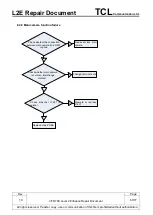
Page 40: ...inutes check whether can power on Replace side key FPC N N Reweld or Replace s i d e k e y F P C connector Y Check whether battery status is good N Replace it with a new battery Y Check whether back cover is assembled well N Reassemble the back cover Y Check whether the connection between battery and battery connector is good N R e a s s e m b l e t h e battery Y Check whether battery connector is...

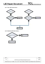
Page 41: ... is prohibited without authorization 7 2 Charge issue Replace battery N N N Check whether the voltage of the battery is 0V and Charge for 15 minutes check whether battery is good C h e c k w h e t h e r b a t t e r y connector is good Check whether USB connector is normal Reweld or replace USB connector replace battery connector Y Y Y Charging failure Y Replace PCBA ...

Page 42: ... file is prohibited without authorization 7 3 Display issue Check whether the connection b e t w e e n LCD a n d LCD connector is good N N Check whether LCD connector is normal Y Check whether Furnished Underfilling is normal interchange method N Reassemble LCD Reweld or replace LCD connector C h a n g e Furnished Underfilling Y Y Replace PCBA Display failure Y ...

Page 43: ...e or communication of this file is prohibited without authorization 7 4 Vibrator issue N Check whether contact of PCBA is clean Y Clean the contact of PCBA Y Y Replace PCBA Vibrating function failure Y Check whether the connection between Vibrator and PCBA is good N Reassemble Vibrator N Change Vibrator Check whether Vibrator is normal ...

Page 44: ...ed without authorization 7 5 Touch panel issue Y Y Y Replace PCBA Touch function failure N C h a n g e Furnished Underfilling Check whether Furnished Underfilling i s n o r m a l interchange method N Reweld or replace TP connector Check whether TP connector is normal Y N Reassemble the TP C h e c k w h e t h e r t h e connection between TP a n d T P c o n n e c t o r i s normal ...

Page 45: ...d Transfer copy use or communication of this file is prohibited without authorization 7 6 SIM recognize issue Check whether the SIM card is good N N C h e c k w h e t h e r S I M c a r d connector is good Re assemble or change SIM card Re weld or change SIM card connector Y Replace PCBA Y SIM card can t be recognized Y ...

Page 46: ...s reserved Transfer copy use or communication of this file is prohibited without authorization 7 7 TF card recognized issue Check whether the TF card is good N Check whether the TF card connector is good Change TF card Replace PCBA Y T F c a r d c a n t b e recognized Y N Reweld or replace TF card connector Y ...

Page 47: ...ile is prohibited without authorization 7 8 Main camera issue Check whether the connection between main camera and Main camera connector is good N Y N Check whether main camera is normal Y Check whether Main camera connector is normal N Reassemble main camera Replace main camera Reweld or replace Main camera connector Y Replace PCBA Main camera function failure Y ...

Page 48: ...is prohibited without authorization 7 9 Sub camera issue Check whether the connection between sub camera and sub camera connector is good N Y N Check whether sub camera is normal Y C h e c k w h e t h e r s u b c a m e r a connector is normal N Reassemble sub camera Replace sub camera Reweld or replace sub camera connector Y Replace PCBA Sub camera function failure Y ...

Page 49: ... communication of this file is prohibited without authorization 7 10MIC issue Check whether MIC is normal Reweld or replace MIC Y N check whether sub MIC is normal Reweld or replace sub MIC No sound emitting or sometimes no sound emitting noises or echoes were heard by other side during the call recording function failure Y N Replace PCBA Y ...

Page 50: ...ssue Check whether contact of PCBA is clean N Clean the contact of PCBA Check whether speaker is normal N Change speaker Y No ringing or hands free sound failure Y Replace PCBA Y 8 PCBA exchange Before performing the following troubleshooting operations please make sure the software of the device is in good condition and restored to default settings 8 1 Position of L2 enhance components on main PC...

Page 51: ...r Document TCLCommunication Ltd Rev VFD 700 Level 2 Enhance Repair Document Page 1 0 51 77 All rights reserved Transfer copy use or communication of this file is prohibited without authorization Main PCBA Side B ...

Page 52: ...Document TCLCommunication Ltd Rev VFD 700 Level 2 Enhance Repair Document Page 1 0 52 77 All rights reserved Transfer copy use or communication of this file is prohibited without authorization ACF module sub PCBA ...

Page 53: ...e 8H Otherwise it may cause the PCBA blister easily when you heat part of the PCBA by using hot wind gun 2 Interchange method means using a new component to test the function in order to verify whether the old component is defected 3 Please use hot wind gun to reweld or disassemble assemble the component mentioned afterwards hot wind gun temperature 330 Air Level 2 3 Height around 10mm Time less t...

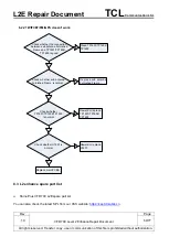
Page 54: ...is file is prohibited without authorization Check whether the connection between LCD FPC and J1102 is good N Y Check whether LCD is n o r m a l i n t e r c h a n g e method N Y Reassemble LCD Change LCD Replace Main PCBA Check whether J1102 is normal N Reweld or replace J1102 Y Check whether U1101 is normal N Reweld or replace U1101 Y 8 2 2 No keypad backlight ...

Page 55: ...zation Y Check whether H1201 is normal N Reweld or replace H1201 Y No back key backlight Y No recents key backlight Replace main PCBA N Reassemble ACF module Check whether the connection between ACF module and J1205 are good Reweld or replace J1205 N Y N Reweld or replace H101 Check whether H101 is normal Y Check whether J1205 is normal Y N Replace ACF module Check whether ACF module is normal Y ...

Page 56: ... without authorization 8 2 3 Power on failure Check whether side key FPC is normal N Y N Y Check whether J0901 is normal N Replace side key FPC Replace new battery and check the charge function etc Reweld or replace J0901 Check whether battery is normal such as volt etc Y Replace Main PCBA Check whether the connection between side key FPC and J1204 is good N Y Reassemble side key ...

Page 57: ...unction failure Check whether the connection between TP and J1101 is good N Y N Check whether TP is normal interchange method Y Check whether J1101 is normal N Reassemble TP Change TP Reweld or replace J1101 Replace Main PCBA Y 8 2 5 Voice transmitting failure Replace main PCBA Y Check whether M1501 is normal N Reweld or replace M1501 Y Check whether M1502 is normal N Reweld or replace M1502 Y Mai...

Page 58: ... No Ringing Replace main PCBA Y N Reassemble ACF module Check whether the connection between ACF module and J1205 are good Reweld or replace J1205 N Y N Replace ACF module Check whether ACF module is normal Y Y Check whether J1205 is normal Check whether the connection between speaker and ACF module are good N Reassemble speaker Main antenna Furnished Frame Y N Replace speaker Check whether speake...

Page 59: ...without authorization 8 2 7 SIM card is not recognized Check whether the SIM card is well inserted N Y N Check whether J1202 J1203 is normal Reassemble SIM card Reweld or replace J1202 J1203 Y Replace main PCBA 8 2 8 TF card is not recognized Check whether the TF card is well inserted N Y N Check whether J1201 is normal Reassemble TF card Reweld or replace J1201 Y Replace main PCBA ...

Page 60: ...ommunication of this file is prohibited without authorization 8 2 9 Main camera function failure Check whether the connection between main camera and J1401 is good N Y Reassemble main camera Y Check whether main camera is normal interchange method N Change main camera Check whether J1401 is normal N Reweld or replace J1401 Y Replace main PCBA ...

Page 61: ...tion of this file is prohibited without authorization 8 2 10 Sub camera function failure Check whether the connection between front camera and J1402 is good N Y Reassemble front camera Y Check whether front camera is normal interchange method N Change front camera Check whether J1402 is normal N R e w e l d o r r e p l a c e J1402 Y Replace main PCBA ...

Page 62: ...e is prohibited without authorization 8 2 11 Flash LED function failure Y Check whether H1401 H1402 is normal N Reweld or replace H1401 H1402 Y Check whether H1403 is normal N Reweld or replace H1403 Y Main flash LED Y Front flash LED Replace main PCBA 8 2 12 Indication LED function failure Y Check whether H0801 is normal N Reweld or replace H0801 Replace main PCBA ...

Page 63: ...eck whether J101 is normal N Reweld or replace J101 Check whether charging indicator displays OK N Y N Replace new battery and check the charge function etc Check whether battery is normal such as volt etc Y Check whether J0901 is normal N Reweld or replace J0901 N Check whether the connection between ACF module and J1205 are good Y Y Y N Check whether ACF module is good Replace ACF module Reassem...

Page 64: ...thout authorization 8 2 14 USB is not recognized Replace main PCBA Check whether USB cable is normal N Replace USB cable Y Y Check whether J101 is normal N Reweld or replace J101 N Check whether the connection between ACF module and J1205 are good Y Y N Check whether ACF module is good Replace ACF module Reassemble ACF module Y Check whether J1205 is normal N Reweld or replace J1205 ...

Page 65: ...Light Proximity Sensor function failure N Reweld or replace U1302 Check whether U1302 is normal Y Replace main PCBA 8 2 16 No finger print function N Check whether the connection between Furnished Underfilling and J1206 are good Y Y N Check whether Furnished Underfilling is good Replace Furnished Underfilling Reassemble Furnished Underfilling Replace main PCBA Y Check whether J1206 is normal N Rew...

Page 66: ...eweld or replace U1301 Check whether U1301 is normal Y Replace main PCBA 8 2 18 No NFC function N Reweld or replace TP2203 TP2204 Check whether TP2203 TP2204 is normal N Check whether the connection between Sub antenna Furnished Frame and TP2203 TP2204 is good Y Clean TP2203 TP2204 N Replace Sub antenna Furnished Frame Check whether Sub antenna Furnished Frame is normal Y Y Replace main PCBA N Rew...

Page 67: ...Page 1 0 67 77 All rights reserved Transfer copy use or communication of this file is prohibited without authorization 8 2 19 Headset failure Check whether J1501 is normal N Reweld or replace J1501 Y Check whether headset is normal N Y Replace headset Replace main PCBA 8 2 20 No signal ...

Page 68: ...antenna Furnished Frame and TP1901 TP1902 TP1903 TP1904 is good Y Clean TP1901 TP1902 TP1903 TP1904 N Replace main antenna Furnished Frame Check whether main antenna Furnished Frame is normal Y Y N Reweld or replace TP2101 TP2102 TP2103 TP2104 Check whether TP2101 TP2102 TP2103 TP2104 is normal N Check whether the connection between sub antenna Furnished Frame and TP2101 TP2102 TP2103 TP2104 is go...

Page 69: ... whether TP1601 TP1602 TP1603 is normal N Check whether the connection between sub antenna Furnished Frame and TP1601 TP1602 TP1603 is good Y Clean TP1601 TP1602 TP1603 N Replace sub antenna Furnished Frame Check whether sub antenna Furnished Frame is normal Y Y N Reweld or replace U1601 Check whether U1601 is normal Y Replace main PCBA 8 3 L2 enhance spare part list Shine Plus VFD 700 L2E spare p...

Page 70: ...A without accessories LCD and camera Main Sub MIC are enclosed when exchange the PCBA 2 Get a new PCBA from the swap stock Reuse those accessories to assemble the mobile 3 Fill in the record sticker with IMEI number fault code short code Hardware Technical Level and software version 4 Send the NG PCBA with record sticker back to L3 repair center with the recommended packaging method Note packaging...

Page 71: ...need to be very careful to handle the components with related special tool or jig especially replacing new components It is better to handle it with plastic tools plastic tweezers and wedge etc Besides operator must wear anti static gloves fingertips or wear static loop during the whole process of components exchange Function Test During the function test the following items must be checked and va...

Page 72: ...use or communication of this file is prohibited without authorization APPENDIX 1 Packaging Requirements 1 Any L3 PCBA which has appearance like below cases is not acceptable 1 The PCBA which shielding cover is rusty or distortion copper peel off 2 Smudge on PCBA such as soldering flux rudimental glue handwriting burn scratch and so on ...

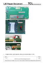
Page 73: ...Ltd Rev VFD 700 Level 2 Enhance Repair Document Page 1 0 73 77 All rights reserved Transfer copy use or communication of this file is prohibited without authorization 3 Symptom sticker high temperature adhesive or nonstandard label on PCBA ...

Page 74: ...munication of this file is prohibited without authorization Note a Nonstandard label means broken label label with handwriting dirty label label pasted in the wrong place etc b L2E label IMEI label and PCBA label are acceptable to be kept on PCBA only under the condition that these labels are intact clean and smoothly pasted in the right place ...

Page 75: ...ument Page 1 0 75 77 All rights reserved Transfer copy use or communication of this file is prohibited without authorization 4 PCBA with liquid or mildew 2 PCBA label must be retained on the PCBA Clean and intact IMEI label should be retained on the PCBA IMEI label PCBA label Note ...

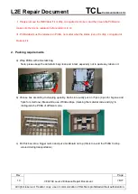
Page 76: ...ined on PCBA no matter what the status even it is dirty corrugated or broken it is 2 Packing requirements a Wrap PCBA with anti static bag Note please keep the anti static bag clean and intact especially not to paste any label on it b Choose box according to shipping quantity Each slot usually put 4 or 5pcs 4pcs for big one and 5pcs for small one Meanwhile use Wrinkled tape marking the material co...

Page 77: ... Please send the electronic edition to all relevant receivers departments If possible put the hard copy Excel file of L3 PCBA Symptom description into the carton No Country Project Name Commercial Reference IMEI SN Symptom decription Symptom code 1 eg SPAIN Pisco 916X 2AYGES1 8623870109873 43 can t power on TON If you have any question or problem please feel free to contact us Thanks for your coop...

Reviews: