Factory Test & Alignment Specification For MS08F1-LA Series (V1.1)
Page 5 of 9
L55S4600F
004
LVF550ND2L CD9W00 V3
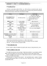
1.4. Functional Test
Once the b oards (chas sis, KB, IR, PSU…) an d the p anel are w ell interconnected, plug all
external generator devices to relevant inputs/outputs below according to their respective test patterns
format and check picture content and sound quality accordingly:
Source
Test Signal
Test Pattern
Analog/Digital Tuner
(VHF/UHF & CATV)
RF cable generator
2D - Movie 1280x720
2D - Static Picture 1920x1080
1. Frequency Range: full band
2. Standard: NTSC /PAL M
3. ISDB-T
SPDIF
(Coaxial)
Audio Amplifier
PCM or Dolby D+
AV IN
(CVBS & AUDIO)
Chroma/Fluke
generator
PAL Half Color & Gray bars
CMP
(YPbPr & Audio)
Chroma/Quantum Data
generator
1920x1080i@60Hz
Half Color & Gray bars
HDMI
(Video & Audio)
with beyond HDMI 1.3
and HDCP compliant
DVD/BD player
2D - Movie 1280x720i@60Hz
RJ45
(LAN)
Internet
ICMP packets echo request
Headphone
via mini jack adapter
RF signal
Suitable channel
Loud Speakers
/ Enclosures
RF signal
Suitable channel
AV OUT
(Audio)
RF signal
Suitable channel
Audio tones can be defined by the factory (i.e. 1 KHz & 3 KHz sweep).
Picture video formats can be changed by the factory according to their own standard.
Remark
:
1. AV Video & Audio in shared with CMP.
1.5. AD Calibration Test
As SoC is built-in an A/D self-calibration mechanism, ADC need not to be performed any more.
1.6. DDC & EDID & T-Link Test
The E-EDID data structures are according to VESA Enhanced EDID 1.3 (and EIA/CEA- 861B for
HDMI). CEA Timing Extension structure has been extended to support all 3D capable timings.
All VGA and HDMI structures have their own BIN profile which are part of main SW and uploaded
at power-on into HDMI switch chipset.
For EDID check, it’ s needed to check whether the correct EDID is down loaded b y checking
corresponding EDID NVM Checksu m or read t hem out to check bit by bit if i t i s in line with the
released EDID bin file.
Summary of Contents for L40B2800
Page 32: ......


