Colour Television Chassis: M123A
65
10. Circuit Description
(1) Tuner
The function of the tuner is to select the channel to be received and suppress the interference, to amplify the high
frequency signal, to improve the receiving sensitivity and SNR, to generate PIF signal through frequency conversion.
(2) IF Channel
The IF Channel mainly ensures the sensitivity and selectivity of the complete machine. The IF AMP integrated in
TMPA8802 is made up of the third-stage dual-differential amplifier with gain value above 70db, SNR of 55dB and
bandwidth of 6MHZ. The video demodulation circuit is made from the built-in PLL Sync Detector. The spectrum of the
demodulation carrier is unitary and not affected by the content of the video signal. The tuner features stable receptivity
while the signal output from the video detector features high fidelity.
PLL built-in TMPA8802 generates 45.75MHz demodulation reference signal for sync detector to demodulate the video
signal, which is called 'PLL sync demodulation'.
(3) Chroma Signal Decoding Circuit
Through the external BPF (band-pass filter) to single out the chroma signal and burst signal within the range of
fsc+1.3MHZ from among the composite signals output from the video detector. After being amplified by ACC, the chroma
signal is fed into the synchronous detector to be demodulated to obtain the color difference signal.
(4) Luminance Channel and Matrix Circuit
The luminance channel of TMPA8802 has the black stretch circuit to make the 'darkish' ingredient of the picture turn '
atrous ', thus improve the contrast and depth perception of the picture. It also has the delayed definition-enhanced circuit
to enable the details of the picture more vivid. The luminance signal (Y) is sent into the matrix circuit after being delayed
for 0.6
s and composes R/G/B signal combined with three color-difference signals (B-Y, R-Y, G-Y).
(5) Sync Separation and Deflection Processing Circuit
TMPA8802 has the 32fh PLL (fh = horizontal frequency). In accordance with the frequency and phase information carried
by composite sync signal, PLL generates scan clock signal with 32fh and horizontal drive pulse will be obtained through
32fh countdown. Use integrating circuit to extract vertical sync signal from the composite sync pulse to control the
counter for vertical countdown. The counter countdown the 32fh clock signal, thus vertical frequency sync pulses under
various systems can be obtained.
TMPA8802 includes the vertical SW former (sawtooth wave former) and can control the gain and linear of SW (sawtooth
wave). Therefore, the vertical amplitude control and the linearity correction of the scanning raster can be achieved by
2
setting the data with remote controller via I C bus input.
(6) Sound Channel
The second SIF goes via a filter of 4.5MHz, to MSP3425. Then decoded by MSP3425, the second SIF turns into sound signal
of MONO, STEREO, and SAP. The sound signal processed by inner sound effect, input to TDA7057AQ and drive the
2
speakers to restore the sound. MONO, STEREO, SAP and sound effect processing modes are adjusted via I C bus.
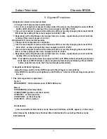
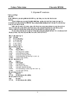
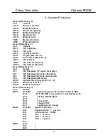
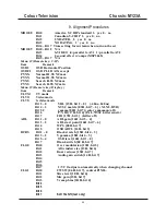
(7) Remote Control System
The MCU (TMPA8802) of an 8-bit CPU and the software constitute the control core of the remote control system, mainly
accomplishing the following functions: decoding remote control commands; auto search memory; displaying characters
& patterns; switching the signal source between AV and TV.
Infrared remote control transmitter is composed of the special single chip and the keyboard system. The transmitter
translates the commands represented by R/C keys into function codes, and separately demodulates the 37.9KHZ carrier
and 940nm infrared ray twice to generate remote infrared transmitting signal delivered by infrared LED. The remote
control distance isn't less than 8 meters.
With infrared LED the remote control system converse the optical signal into electrical signal, which will be amplified and
decoded to restore the codes of the remote control commands for MCU to analyze and execute.
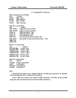
The remote control system has three operating modes: user-controlled mode (U-mode), service mode (S-mode) and
factory default mode (D-mode). U-mode includes the following functions: channel search and memory; channel selecting;
volume control, brightness adjustment, contrast and color adjustment. S-mode and D-mode are mainly used in
production, checking & repairing, including the following functions: horizontal & vertical centering control, vertical
amplitude and linearity adjustment; setting the adjusting range for volume, contrast, brightness, tint and color;
geometric adjustment and white balance adjustment.
(8) CRT Drive Circuit
Adopting the cascode to amplify voltage and current of R/G/B signal, the CRT drive circuit is able to demodulate the
cathode beam current of the CRT. The R/G/ B signal input into the cascode circuit is of negative polarity.
(9) Power Supply Circuit
The circuit supplies various stabilized operating voltages and safeguard protections.
Summary of Contents for CTR1042
Page 41: ...Colour Television Chassis M123A 41 6 Block Diagram and I2C 6 1 Block Diagram...
Page 49: ...Colour Television Chassis M123A 49 7 Electrical Diagrams 7 10 CRT Panel...
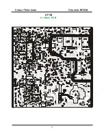
Page 52: ...Colour Television Chassis M123A 52 8 PCB 8 1 Main PCB...
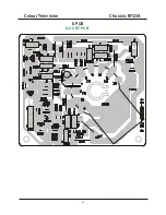
Page 53: ...Colour Television Chassis M123A 53 8 PCB 8 2 CRT PCB...
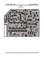
Page 54: ...Colour Television Chassis M123A 54 8 PCB 8 3 MPX PCB...
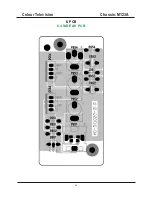
Page 55: ...Colour Television Chassis M123A 55 8 PCB 8 4 SIDE AV PCB...


