TCL AC-07CK Service Manual Download Page 102

Leakage /Freon - 2/4

Case-2

Key Factor

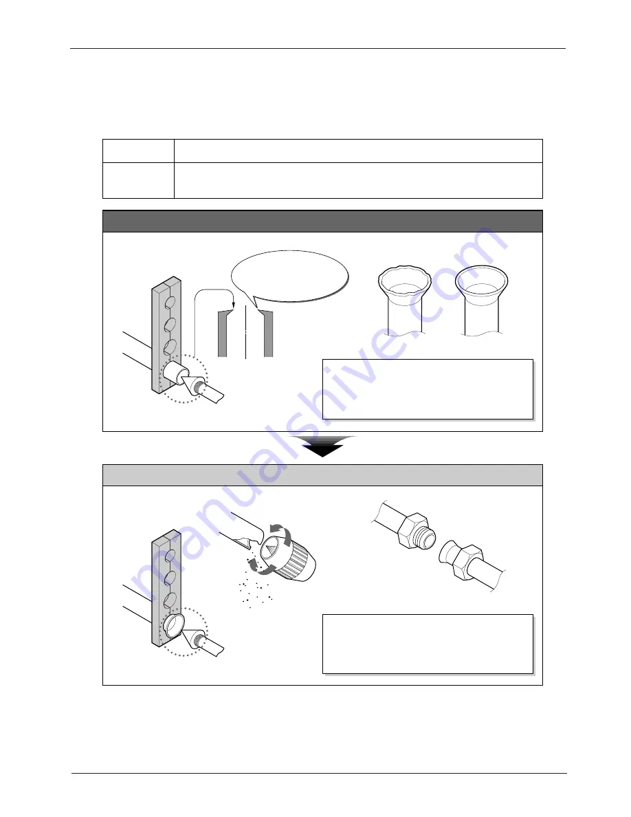
Removing burrs of pipes.

Gas Leaks due to the burrs caused by cutting and not removing properly.

Troubles &

Causes

Defect Details

Guidelines

Reamer

• Burrs should be removed clearly with REAMER.

• Only clean surfaces prevent gas leakages.

Burrs not removed properly

after cutting.

• Flaring the pipe with burrs(not removed after cutting)

can make freon gas leakages.

• Burrs won't make smooth contacting surfaces.

TCL Air Conditioner Service Manual

21

Summary of Contents for AC-07CK

Page 1: ...PLOSION VIEW 29 9 PARTS LIST 33 10 ANNEX 1 THERMISTOR CHARACTERISTIC 11 ANNEX 2 GENERAL 12 ANNEX 3 TROUBLE SHOOTING 13 ANNEX 4 R407C REFRIGERANT Models TAC 07CS K TAC 07CHS K TAC 09CS K TAC 09CHS K TA...

Page 2: ...formation nor can it assume any liability in connection with its use The information specifications and parameter are subject to change due to technical modification or improvement without any prior n...

Page 3: ...system Microcomputer controlled reverse system Fan System Indoor air circulation m3 h 430 430 430 430 Indoor fan type Cross flow Cross flow Cross flow Cross flow Cooling rpm 1000 950 900 1000 950 900...

Page 4: ...mputer controlled reverse system Fan System Indoor air circulation m 3 h 480 480 480 480 Indoor fan type Cross flow Cross flow Cross flow Cross flow Cooling rpm 1230 1150 1000 1230 1150 1000 1230 1150...

Page 5: ...r controlled reverse system Fan System Indoor air circulation m 3 h 530 530 800 850 800 850 Indoor fan type Cross flow Cross flow Cross flow Cross flow Cooling rpm 1150 1060 900 1150 1060 900 1300 120...

Page 6: ...em Microcomputer controlled reverse system Fan System Indoor air circulation m 3 h 550 550 730 730 Indoor fan type Cross flow Cross flow Cross flow Cross flow Cooling rpm 1230 1150 1000 1230 1150 1000...

Page 7: ...e system Fan System Indoor air circulation m 3 h 1000 1000 1000 1000 Indoor fan type Cross flow Cross flow Cross flow Cross flow Cooling rpm 1300 1200 1100 1300 1200 1100 1300 1250 1150 1300 1250 1150...

Page 8: ...K J D E Unit mm Capacity A B C D E F G H I J K 7K 9K 710 250 179 600 500 231 271 296 52 365 55 12K 770865 250 179 700 540 255 290 320 40 439 55 18K 1036 313 204 760 540 255 340 370 62 635 63 24K 1036...

Page 9: ...exchanger Refrigerant flow in cooling or Defrosting Refrigerant flow in heating Distributor Reversing valve 4 way valve Cooling Only INDOOR UNIT OUTDOOR UNIT Refrigerant pipe Optional with heat insula...

Page 10: ...y Outdoor unit precharged up to 7m 15m 160 7m 0 10m 60 07K 09K 12K 18K MAX HEIGHT DIFFERENCE ADDITIONAL REFRIGERANT CHARGE R 22 g MAX REFRIGERANT PIPING LENGTH Calculation Xg 20g m A 7 m Calculation X...

Page 11: ...ter of the gage manifold valve remains in the same position Check the vacuum with the gage manifold valve then close the gage manifold valve and stop the vacuum pump Run the vacuum pump for more than...

Page 12: ...r wet dry bulb temperature and the indoor outlet air wet dry bulb temperature for your reference at service How to measure the indoor air wet bulb dry bulb temperature difference 1 Attach at least 2 s...

Page 13: ...15 1 12 9 28 0 25 9 23 7 21 6 19 4 17 2 15 1 12 9 19 9 18 4 16 9 15 3 13 8 12 3 10 7 9 2 24 NOTE The above curves are for the heating operation without any frost OUTDOOR LOW PRESSURE AND OUTDOOR UNIT...

Page 14: ...dity Outdoor unit current A 220 240V 220 240V kgf F G MPa G kgf F G MPa G 0 7 0 6 0 5 0 4 0 3 0 2 7 6 5 4 3 2 18K 18K Outdoor low pressure Ambient temperature C Ambient humidity Ambient temperature C...

Page 15: ...14 5 C 18K Outdoor unit current A Outdoor unit current A Outdoor unit current A Outdoor unit current A Ambient temperature C Ambient temperature C Ambient temperature C Ambient temperature C 220V 240V...

Page 16: ...1 1 1 TCL Air Conditioner Service Manual Operation Details Remote Controller presetting er presetting presetting as Cooling Only Air Conditioner or Heat Pump by manufacturer Each time after the remote...

Page 17: ...ol During HEATING operation the outdoor fan motor and compressor are controlled by the indoor pipe temperature to prevent the high temperature of compressor Outdoor fan OFF 52 Outdoor fan ON 48 Compre...

Page 18: ...be controlled 5 HEATING Mode Operation Only available for Heat Pump 1 When the HEATING mode is selected without setting temperature the system will set the temperature at 23 automatically with the AU...

Page 19: ...10 minutes Defrosting time chart Outdoor Fan ON OFF ON Revering Valve ON OFF ON Compressor Relay ON OFF ON OFF ON 39S 5S Defrost Count MAX 12min 19S 15S t 6 Assistant Thermistor Function Assistant th...

Page 20: ...cessor to feedback the rotational frequency Comparing the current rotational frequency with the target rotational frequency the microprocessor adjusts fan motor electric to make the current rotational...

Page 21: ...t the time time setting is 30 minutes units After setting the timer check that TIMER INDICATOR lamp of the indoor unit lights Press the ON OFF button for the air conditioner operates in timer the time...

Page 22: ...e failure of indoor pipe temperature sensor Twice cycle E2 Outdoor protection function 5 times cycle E5 The failure of indoor fan 6 times cycle E6 e Failure Handling When the room temperature sensor o...

Page 23: ...Fan Motor Vane Motor M M Indoor Unit Power supply Brown Yellow Green evaporator K1 TH2 TH1 CN6 CN8 CN3 CN4 CN5 3 COM CN1 CN2 4 N O P2 2 P2 1 PCB Brown Blue Yellow Green Outdoor Unit Blue 1 N OUTDOOR U...

Page 24: ...low Blue Yellow Green Display PCB Pipe Temp sensor Room Temp sensor Theimistor Transformer Power Supply Brown Blue PCB CN1 CN2 TH1 TH2 P2 1 P5 P4 P2 2 CN11 CN10 NO K1 COM 4 3 CN8 CN6 CN5 CN4 CN3 M M N...

Page 25: ...OM Relay 1 N N L Display PCB Fan Motor FM SM SM Vane Motor To The Outdoor Room Temp Sensor Pipe Temp Sensor Blue Brown Blue Brown L N 1 2 3 4 1 2 3 4 5 1 2 3 4 5 OUTDOOR UNIT Brown Blue Yellow Green C...

Page 26: ...ay Transformer Fan Motor Vane Motor Room Temp Sensor Pipe Temp Sensor FM SM Display PCB SM Yellow Green Yellow Green Yellow Green Blue Blue Brown Brown L OUTDOOR UNIT Compressor 4 way Vane White CM R...

Page 27: ...SM Vane Motor Display PCB Room Temp Sensor Pipe Temp Sensor 1 2 3 4 4 5 3 2 1 5 4 3 2 1 To Outdoor Unit OUTDOOR UNIT Conpressor White White Yellow Green Blue Brown Yellow Green Brown Blue Blue Brown B...

Page 28: ...n Motor Vane Motor Room Temp Sensor Pipe Temp Sensor To Outdoor Unit 1 2 3 N L 1 2 3 4 5 1 2 3 4 5 4 3 2 1 OUTDOOR UNIT White White Red Yellow Blue Brown Yellow Green White White Red Brown Yellow Gree...

Page 29: ...INDOOR UNIT TAC 07CS K TAC 07CSH K TAC 07CSC K TAC 07CHSC K TAC 09CS K TAC 09CHS K TAC 09CSC K TAC 09CHSC K TAC 12CS K TAC 12CHS K TAC 12CSC K TAC 12CHC K 1 2 3 5 14 6 7 8 9 10 15 16 17 18 19 20 21 2...

Page 30: ...tioner Service Manual 30 INDOOR UNIT TAC 18CS K TAC 18CSC K TAC 18CHS K TAC 18CHSC K TAC 24CS K TAC 24CSC K TAC 24CHS K TAC 24CHSC K 1 2 3 4 5 6 7 8 9 10 11 12 13 29 28 27 26 25 24 23 22 21 20 19 18 1...

Page 31: ...nditioner Service Manual 31 Outdoor Unit TAC 07CS K TAC 07CSC K TAC 09CS K TAC 09CSC K TAC 12CS K TAC 12CSC K TAC 18CS K TAC 18CSC K TAC 24CS K TAC 24CSC K 1 2 3 5 4 6 7 9 10 11 12 13 14 15 16 17 20 2...

Page 32: ...tioner Service Manual 32 Outdoor Unit TAC 07CHS K TAC 07CHSC K TAC 09CHS K TAC 09CHSC K TAC 12CHS K TAC 12CHSC K TAC 18CHS K TAC 18CHSC K TAC 24CHS K TAC 24CHSC K 1 2 3 4 5 6 7 9 10 11 12 13 14 15 16...

Page 33: ...ard Cover 1 15 1170120042 Power Supply Cord 1 16 1070250103 Vane 1 17 1070110008 Drainage Hose 1 18 1070040006 Electrical Box Cover 1 19 1070040004 Cable Clamp 1 20 1170200039 Terminal 1 21 1070250109...

Page 34: ...Cover 1 15 1170120042 Power Supply Cord 1 16 1070250103 Vane 1 17 1070110008 Drainage Hose 1 18 1070040006 Electrical Box Cover 1 19 1070040004 Cable Clamp 1 20 1170200040 Terminal 1 21 1070250109 Ter...

Page 35: ...Cover 1 15 1170120047 Power Supply Cord 1 16 1070320104 Vane 1 17 1070110008 Drainage Hose 1 18 1070040006 Electrical Box Cover 1 19 1070040004 Cable Clamp 1 20 1170200039 Terminal 1 21 1070250109 Ter...

Page 36: ...Cover 1 15 1170120047 Power Supply Cord 1 16 1070320104 Vane 1 17 1070110008 Drainage Hose 1 18 1070040006 Electrical Box Cover 1 19 1070040004 Cable Clamp 1 20 1170200040 Terminal 1 21 1070250109 Te...

Page 37: ...over 1 15 1170120047 Power Supply Cord 1 16 1070320104 Vane 1 17 1070110008 Drainage Hose 1 18 1070040006 Electrical Box Cover 1 19 1070040004 Cable Clamp 1 20 1170200039 Terminal 1 21 1070250109 Term...

Page 38: ...Cover 1 15 1170120047 Power Supply Cord 1 16 1070320104 Vane 1 17 1070110008 Drainage Hose 1 18 1070040006 Electrical Box Cover 1 19 1070040004 Cable Clamp 1 20 1170200040 Terminal 1 21 1070250109 Ter...

Page 39: ...ical Box Cover 1 16 1170120006 Power Supply Cord 1 17 1073090108 Vane A 1 18 1073090125 Vane B 1 19 1070110008 Drainage Hose 1 20 1070040003 Cable Clamp 2 21 1170020011 Vane Motor 1 22 1170200038 Term...

Page 40: ...trical Box Cover 1 16 1170120006 Power Supply Cord 1 17 1073090108 Vane A 1 18 1073090125 Vane B 1 19 1070110008 Drainage Hose 1 20 1070040003 Cable Clamp 2 21 1170020011 Vane Motor 1 22 1170200040 Te...

Page 41: ...scharge Pipe 1 13 1123521402 Suction Pipe 1 14 1213530414 Base 1 15 1120120008 Two way Valve 1 16 1080050014 Valve Supporter 1 17 1120130011 Three way Valve 1 18 1080050013 Right Plate 1 19 1073521301...

Page 42: ...1120250608 Discharge Pipe 1 13 1123521402 Suction Pipe 1 14 1210500106 Base 1 15 1120120017 Two way Valve 1 16 1080050003 Valve Supporter 1 17 1120130025 Three way Valve 1 18 1080050002 Right Plate 1...

Page 43: ...3521402 Suction Pipe 1 14 1213530414 Base 1 15 1120120008 Two way Valve 1 16 1080050014 Valve Supporter 1 17 1120130011 Three way Valve 1 18 1080050013 Right Plate 1 19 1073521301 Electrical Box Cover...

Page 44: ...bly 1 13 1210320103 Base 1 14 1120120017 Two way Valve 1 15 1080050003 Valve Supporter 1 16 1120130025 Three way Valve 1 17 1080050002 Right Plate 1 18 1073551103 Electrical Box Cover 1 19 1080020001...

Page 45: ...e Pipe 1 13 1120320702 Suction Pipe 1 14 1210320103 Base 1 15 1120120016 Two way Valve 1 16 1080050003 Valve Supporter 1 17 1120130021 Three way Valve 1 18 1080050002 Right Plate 1 19 1073551103 Elect...

Page 46: ...250608 Discharge Pipe 1 13 1123521402 Suction Pipe 1 14 1210500106 Base 1 15 1120120017 Two way Valve 1 16 1080050003 Valve Supporter 1 17 1120130018 Three way Valve 1 18 1080050002 Right Plate 1 19 1...

Page 47: ...e Assembly 1 13 1210320103 Base 1 14 1120120016 Two way Valve 1 15 1080050003 Valve Supporter 1 16 1120130021 Three way Valve 1 17 1080050002 Right Plate 1 18 1073551103 Electrical Box Cover 1 19 1080...

Page 48: ...13 1210500106 Base 1 14 1120120017 Two way Valve 1 15 1080050003 Valve Supporter 1 16 1120130018 Three way Valve 1 17 1080050002 Right Plate 1 18 1073551103 Electrical Box Cover 1 19 1080020001 Electr...

Page 49: ...00101 Suction Pipe 1 14 1210500106 Base 1 15 1120120016 Two way Valve 1 16 1080050003 Valve Supporter 1 17 1120130021 Three way Valve 1 18 1080050002 Right Plate 1 19 1073551103 Electrical Box Cover 1...

Page 50: ...120700103 Discharge Pipe 1 14 1214561809 Base 1 15 1120120011 Two way Valve 1 16 1084530502 Valve Supporter 1 17 1120130013 Three way Valve 1 18 1084530503 Right Plate 1 19 1074530503 Electrical Box C...

Page 51: ...0106 Base 1 14 1120120016 Two way Valve 1 15 1080050003 Valve Supporter 1 16 1120130021 Three way Valve 1 17 1080050002 Right Plate 1 18 1073551103 Electrical Box Cover 1 19 1080020002 Electrical Part...

Page 52: ...1214561809 Base 1 14 1120120011 Two way Valve 1 15 1084530502 Valve Supporter 1 16 1120130013 Three way Valve 1 17 1084530503 Right Plate 1 18 1074530503 Electrical Box Cover 1 19 1084561802 Electrica...

Page 53: ...n Pipe 1 13 1120700103 Discharge Pipe 1 14 1214561809 Base 1 15 1120120011 Two way Valve 1 16 1084530502 Valve Supporter 1 17 1120130013 Three way Valve 1 18 1084530503 Right Plate 1 19 1074530503 Ele...

Page 54: ...120700103 Discharge Pipe 1 14 1214561809 Base 1 15 1120120011 Two way Valve 1 16 1084530502 Valve Supporter 1 17 1120130013 Three way Valve 1 18 1084530503 Right Plate 1 19 1074530503 Electrical Box C...

Page 55: ...ssembly 1 13 1214561809 Base 1 14 1120120011 Two way Valve 1 15 1084530502 Valve Supporter 1 16 1120130013 Three way Valve 1 17 1084530503 Right Plate 1 18 1074530503 Electrical Box Cover 1 19 1084561...

Page 56: ...1214561809 Base 1 14 1120120011 Two way Valve 1 15 1084530502 Valve Supporter 1 16 1120130013 Three way Valve 1 17 1084530503 Right Plate 1 18 1074530503 Electrical Box Cover 1 19 1084561802 Electrica...

Page 57: ...le of refrigerating cycle 4 Definition of terms 5 The term of unit 6 The term of function 7 Mollier diagram 8 Psychrometric chart 9 Noise characteristics 10 Load calculation 11 The coordination coeffi...

Page 58: ...ling Heating Heat pump Window Window Skinny PTAC Split Split Floor Standing Multi Cassette Duct Convertible 27 c 20 c 40 c Cooling Cooling Heating 19 c Cassette Split Window Floor Standing Skinny Conv...

Page 59: ...te air flow and keep uniformly the temperature humidity condition of room unit Standard for feeling comfortable 3 Principle of refrigerating cycle 3 1 Principle of refrigerating It is as follows 1 Spr...

Page 60: ...easy to evaporate 4 Evaporation The liquid refrigerant of low temperature and low pressure passed though the capillary tube absorbs the room air heat in evaporator and evaporates into a gas MOTOR COM...

Page 61: ...substance with its temperature constant is called latent heat whereas heat which changes the temperature of a substance is called sensible heat Latent heat is expressed in terms of calo ries needed t...

Page 62: ...xpressed in calorie required to freeze water 1 Ton water 32 F 2000 lb into ice 32 F and when using the solidification latent heat of water 1RT is as follows 1 RT 144BTU lb x 2000 lb 24hr 12 000 BTU hr...

Page 63: ...temperature and low pressure The type of capillary is generally a thin and long copper tube of 0 6 2 0mm2 inner diameter and 1 2m long The resistance of tube causes to turn into a liquid of low pres s...

Page 64: ...e switch H P S W A protective device of automatic return type which protects compressor from overload by sensing the discharge pressure of compressor working at an abnormal high temperature and shutti...

Page 65: ...le of multi model 20 Check valve Prevent refrigerant from reverse flow in refrigerating cycle It is installed in a place where it is necessary to prevent the reverse flow of refrigerant in a copper pi...

Page 66: ...ition 1 Evaporation condensation temperature Find an evaporation temperature 8 C on the saturated liquid line or saturated vapor line in Mollier diagram and draw a horizontal line isobar line pressure...

Page 67: ...rcooling 6 C 5 State of expansion valve outlet The state of evaporator inlet The state is changed on isentropic line with out thermal input output in expansion valve so the state point is the intersec...

Page 68: ...g effect and the heat equivalent of work Figure 7 10 qe qe Al qe iA iD iB iA iB iD 7 5 7 3 Calculation of refrigerating cycle 1 Refrigerating effect Calories which evaporator absorbes and the refriger...

Page 69: ...is calculated as follows D Diameter of cylinder m n Rotational speed of compressor rpm L Piston stroke m N No of cylinder 5 Coefficient of performance The efficiency of refrigerating cycle It is expre...

Page 70: ...8 5kcal kg iC 110kcal kg iD 110kcal kg iC iD 112kcal kg iE 148kcal kg Accordingly Refrigerating effect q1 iA iD 148 5 110 38 5 kcal kg Work of compression A1 iB iA 158 5 148 5 10 kcal kg Calorie of co...

Page 71: ...9 30 20 10 0 10 20 30 40 50 60 70 80 t 90 C t 90 C 50 C 50 C 50 C 1 0 0 C 1 5 0 C 2 0 0 C 0 0 02 100 C 150 C 200 C 1 3 0 1 2 5 1 2 0 0 0 0 3 0 0 0 4 0 0 0 5 0 0 0 6 0 0 0 8 0 01 0 0 6 0 1 0 15 0 2 0...

Page 72: ...cific volume v 0 862 m3 kg 8 2 Discomfort index DI In summer Discomfort Index is frequently used in the weather forecast on TV or newspapers Man feels hot or dry according as the relative humidity is...

Page 73: ...house caused the bedclothes in wardrobe to be damp by de wing or the winter heating caused to form dew on window and waterdrop to flow into wall or floor carpet Dewing prevention Such a fine particle...

Page 74: ...a t i v e h u m i d i t y S a t u r a t e d d e g r e e W e t B u lb t e m p e r a t u r e t C Dry Bulb temperature t C I c e w a t e r Absolute humidity x kg kg DA 40 35 30 Steampartialpressure Pw mm...

Page 75: ...0 L1 L2 10 L1 L L1 L2 The equation is applied to the sound decomposition method When complex sound measured sound is L3 dB and background noise is L2 dB the object sound L1 dB is calculated as follows...

Page 76: ...0 5 Lpd 50 20 log 1 4 38 0 2 Considering the noise source the complex noise level is L 10 log 1044 10 1044 10 1040 5 10 1038 10 1035 10 48 5 dB 9 3 Allowable level of noise 1 NC curve NC curve as an a...

Page 77: ...Latent heat 28 C 27 C 26 C 24 C 21 C SH LH SH LH SH LH SH LH SH LH 44 44 49 39 53 35 58 30 65 23 45 56 49 52 53 48 61 40 69 32 45 68 50 63 54 59 62 51 72 41 45 81 50 76 55 71 64 62 73 53 48 91 56 83...

Page 78: ...0 5 1 5 7 4 2 3 Double window Without pent roof unit m Entrance door Opening shutting door Wall inner wall Living room Wall No sunshine North Condition Apartment living room middle layer 4 persons in...

Page 79: ...area subtract the window area 2 All of each outer wall to the directions east west south with sunshine is calculated as sunshine and the outer wall to north or shade direction is calcu lated as north...

Page 80: ...r over Western or southern room Many persons in a room Heater in a room 3 Rough selection of capacity Considering the above 2 add the clearance rate by 10 each except for lecture room kitchen or speci...

Page 81: ...ople occupy area add 600 BTU Hr per person If only one person subtract 600 BTU HR How to read the cooling Selection Guide 1 Determine area to be cooled in sqare feet Locate that point on the left side...

Page 82: ...ANNEX 3 TROUBLE SHOOTING INDEX 1 Electric parts 2 Refrigerant system 3 Troubleshooting 4 Installation Fundamentals TCL Air Conditioner Service Manual...

Page 83: ...Usable voltage Product rating 10 2 Electric wire capacity The electric wire for airconditioner should have an allowable current more than the load current of the circuit and be able to control the vol...

Page 84: ...Insulation resistance measurement of compressor Measure the insulation resistance of compressor between compressor terminal and dead metal part by insu lation resistor and the insulation resistance s...

Page 85: ...ee kinds of dial vibrating direction in tester and each vibrating direction and symptom is as follows A Normal Dial shakes instantaneously and returns to the original state immediately B Short Dial re...

Page 86: ...f knob is turned but click does not sound remove the thermostat cover and examine the contact point The fused contact point should be replaced with a new thermostat If contact point is not closed desp...

Page 87: ...tor inside and for a single phase compressor with O L P built in it identifies the O L P operating condition and wire disconnection 1 Shut off the power supply to product 2 Remove the wires connected...

Page 88: ...erature of discharge pipe in compressor and if it is abnormally low temperature 50 C or less the compressor is bad c Conduct the pump down test of system to check the compression capacity Power off th...

Page 89: ...n indoor unit Adjust the wind direction so that wind is discharged to the front direction in the installed condition b Measure the voltage and current in running condition c Measure the pressure of lo...

Page 90: ...ure converted into pressure The low pressure is normally 4 5 6 0kg cm2G Temperature is normally 3 C 10 C Indoor Side Outdoor Side Evaporator Compressor Capillary Tube High pressure Liquid side tube Lo...

Page 91: ...comes out from the evaporator condenser connections and each welded portion Finding the gas leak place 3 Actions Find the gas leak area Check at balance pressure of 5kg cm2 G or over Charge refrigera...

Page 92: ...eck for gas leak 4 Bad compression 1 Symptoms The temperature difference of suction discharge air is little the running current is less than the specified current the pressure of high pressure side is...

Page 93: ...d direct the direction where nobody exists 2 Do not work near fire or flame 3 Work in a large space if possible and arrange the scaffold 4 Especially for working on rooftop prepare a place to keep too...

Page 94: ...tage Driving load terminal Display PCB connector Power receptable voltage Product input voltage Evaportor condenser connecting pipe PCB assy fuse varistor pattern AC about 14 3V General model Connecto...

Page 95: ...capacitor Communication effor Blower lock sensing In dehumidifying heating or artificial intelligence operation room fan may be off Coil resistance TP Motor capacitor Motor insulation resistance Motor...

Page 96: ...sor open close check Connector check Contact power Disconnection short circuit check of connecting wire Electric wire connection check for outdoor side Compressor motor detail check Repeat running sto...

Page 97: ...At the moment the blower is stopped up down vane auto switch is stopped and if blower is started auto switch is re operated Especially it occurs while dehumidifying or heating Motor shaft assembly che...

Page 98: ...room fan is stopped louver auto swing is stopped and if room fan is started auto swing is re operated Especially it occurs while dehumidifying or heating Motor shaft assembly check Connector check Di...

Page 99: ...compressor is stopped blower is operated at low fan In dehumidifying mode to enhance the dehumidifying effect blower is operated at low fan In heating mode blower is stopped or operated at low fan acc...

Page 100: ...ration by remocon and after about 30 sec check the 4 way valve relay output 4 way valve OFF If 4 way valve is OFF the refrigerant flowing sounds pee due to cycle switchover occurs If the reversing val...

Page 101: ...ed copper pipes with non rectangular section Troubles Causes Defect Details Guidelines Pipe cutter Pipe cutter Make pipe straight before cutting and it makes a rectangular section Cu pipe Cu pipe Cutt...

Page 102: ...bles Causes Defect Details Guidelines Reamer Burrs should be removed clearly with REAMER Only clean surfaces prevent gas leakages Burrs not removed properly after cutting Flaring the pipe with burrs n...

Page 103: ...zes for several pipes which make proper connectings a Pipe dia b Hight c Flared dia Pipe worked with large sized b won t be assemsled into the nut Pipe worked with small sized b will make small contac...

Page 104: ...wrench is required for proper fastenings Check gas leakages of 4 fastened points and welded points with soap bubbles ctc High pressure points amid compressor s running Low pressure points amid compres...

Page 105: ...For a better drain the install plate may be tilted 2 3 to drain pan s drain side Install plate Weight Confirm the water draining is good or not by poring water into the drain pan Connecting parts of d...

Page 106: ...auses Defect Details Guidelines Connect the extending hose outside and seal with bond and finish by taping Install the drain hose straightened and downward 2 Curved or upward drain hose 1 Improperly e...

Page 107: ...d ending Troubles Causes Defect Details Guidelines The wall through hole should be downward Don t make drain hose clogged with water 2 Clogged drain hose with water 1 Upwarded drain hose along the wal...

Page 108: ...etely insulate weak points like pipe connection and hidden parts Ceiling Hidden parts like behind the ceiling is a weak point too 2 Un insulated hidden parts 1 Incomplete insulation works on tube conn...

Page 109: ...ect Details Guidelines Make U trap against the waterdrop inflow tapings should be upward form downside Outdoor unit Indoor unit U trap 1 Pipe from upside lead waterdrops rain drainage etc into the roo...

Page 110: ...ng tubings For a simple check of proper freon quantity com pare the in and out air temperature after 15 m in from com pressor s running Air in Detect the gas leakages before insulation tubing confirm...

Page 111: ...Guidelines Ensure the distance needed for air flows Bad air flows lead cooling capacity s drop The product may not run normally as the accumulated heat make compressor stop by protecting device s wor...

Page 112: ...s Guidelines Ensure not to disturb the air intake flows Ensure not to disturb the air discharge flows The awning is recommended for a optimum cooling 1 The space for air intake is too narrow Closed ai...

Page 113: ...oor unit Troubles Causes Defect Details Guidelines Discharged air should be outward and not disturbed Establish a proper awning 1 The outdoor shut in a verandah does not work normally The air around t...

Page 114: ...es To get a good shaped tube after bending use specified spring or bending tools In changing air conditioning unit the tubes too should be changed with proper ones 1 Crushed tube by improper bending w...

Page 115: ...Installed too high beyond recommended height difference between indoor and outdoor unit Higher than recommended Nth 3rd 2rd 1st floor Recommending maximum distances between indoor and outdoor unit RAC...

Page 116: ...Guidelines 1 Unstable installed outdoor unit 2 Released fittings and fasteners Slanted Parallel Duct Indoor unit Install the unit balanced stably using specified legs etc To prevent vibrations and no...

Page 117: ...ect Details Guidelines Unstable fixing of surplus tubings will make vibrations and noises during the compressor s running Fixing band Cut away the surplus tubings But if there are any surplus tubings...

Page 118: ...crews of electric power lines It can be led to critical accidents 2 Wiring mistake of fan s electric power lines for outdoor Fan rotates reversely and the unit will be shutdown with overload Air disch...

Page 119: ...for the troubles be insulation break 1 Outdoor runs on main electric power s supply Short between white and red cables 2 Fuse melts on compressor s running Short between red cable and copper pipe 3 Fu...

Page 120: ...the system Bad smells and gases delivered by drain line Troubles Causes Defect Details Guidelines Discharging bad smells gases Bad smells gases can be discharged through the drain hose Bad smells gase...

Page 121: ...rant in the system will have to be pulled out and stored in a disposal cylinder do not ventilate in ambient 2 Refrigerant charge will have to be done only with liquid phase in order to guarantee prope...

Page 122: ...Temperature trend in evaporate 6 Temperature trend in condenser NOT PERMITTED Only complete refrigerant charge YES Possible partial refrigerant charge Use only HFC detector Use only HCFC detector 2 Ma...

Page 123: ...ANNEX 5 INSTALLATION INSTRUCTION TCL Air Conditioner Service Manual Part 1 Wall mounted Split Type...

Page 124: ...ooling type is available 1 2 2 Weak points 1 A little amount of evaporation heat should circulate a great deal of liquid at the same refrigerating capacity 2 When using for iron steels scale occurs mo...

Page 125: ...high low pressure Putty Vinyl tape Remocon fixture Fixture clamping screw Remocon Refrigerant circuit connection to Indoor Outdoor Chaging of wall through hole Wire pipe finishing Remocon hanger Remo...

Page 126: ...into account and select a place where noise and vibration are minimum 5 Select a place so that the warm air and noise from the air conditioner do not disturb neighbors 6 Rooftop Installations If the...

Page 127: ...hole through the wall for piping connections must be done safely For right rear piping and left rear piping draw a line in the direction of the arrow marked D The meeting point of the two lines is th...

Page 128: ...outdoor unit then put them on pipe tube having completed burr removal not possible to put them on after flaring work Copper pipe 90 Slanted Uneven Rough Bar Copper pipe Clamp handle Red arrow mark Co...

Page 129: ...oks engage into their slots click ing sound C Tape the tubing drain hose and the connecting cable Be sure that the drain hose is located at the lowest side of the bundle Locating at the upper side can...

Page 130: ...r unit pipe Pipe Torque wrench Indoor unit tubing Spanner fixed Connection pipe Flare nut Vinyl tape narrow Adhesive Drain pipe Indoor unit drain hose When extending the drain hose at the indoor unit...

Page 131: ...ghten the flare nut with a wrench G Wrap the insulation material around the connect ing portion Overlap the connection pipe heat insulation and the indoor unit pipe heat insulation material Bind them...

Page 132: ...chassis and push the bottom of tubing holder to be engaged at the bottom of chassis J Indoor unit installation 1 Remove the spacer 2 Ensure that the hooks are properly seated on the installation plate...

Page 133: ...outdoor unit 3 6 1 Connect the cable to the Indoor unit Connect the cable to the indoor unit by connecting the wires to the terminals on the control board indi vidually according to the outdoor unit c...

Page 134: ...casing of electrical fittings are liable to come loose from vibrations to which the unit is subjected during the course of transportation Check them and make sure that they are all tightly fastened I...

Page 135: ...prevent water entering the room 3 Fix the piping onto the wall by saddle or equivalent Trap Seal small openings around pipings with a gum type sealer Trap Trap is required to prevent water from enteri...

Page 136: ...Leak test Connect the manifold valve with pressure gauges and dry nitrogen gas cylinder to this service port with charge hoses Pressurize the system to no more than 150 P S I G with dry nitrogen gas...

Page 137: ...ortant to prevent leakage from the system 5 Replace the service valve caps at both the gas and the liquid side and fasten them tight This completes air purging with a vacuum pump The air conditioner i...

Page 138: ...be removed If the actual pressure are lower than shown the system is most likely undercharged and charge should be added The air conditioner is now ready for use Bolt Tubing connection Outside ambient...

Reviews: