background image

1

1

2

2

3

3

4

4

5

5

6

6

D

D

C

C

B

B

A

A

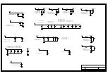
AV_IN/

DI2

NC/AVLC18S02003

CI4

NC/220pF-0402-X7R-±10%-50V

RI4

NC/75ohm-0402-±5%-1/16W

CVBS1_IN

GND

RI3

NC/150ohm-0402-±1%-1/16W

CI3

NC/0.22uF-0402-X5R-±10%-16V

AV_R

GND

AV_RIN

AV_L

GND

AV_LIN

CI15

NC/0.1uF-0402-X5R-±20%-16V

RI23

NC/12Kohm-0402-±5%-1/16W

RI24

NC/12Kohm-0402-±5%-1/16W

RI21

NC/12Kohm-0402-±5%-1/16W

RI22

NC/12Kohm-0402-±5%-1/16W

CI17

NC/0.1uF-0402-X5R-±20%-16V

RXD0/VGA_SCL

TXD0/VGA_SDA

DV7

NC/AVLC18S02003

DV8

NC/AVLC18S02003

GND

SDA_VGA

SCL_VGA

RV19

100ohm-0402-±5%-1/16W

RV18

100ohm-0402-±5%-1/16W

VGA_RIN

VGA_GIN

VGA_BIN

VSYNC

GND

DV1

NC/AVLC18S02003

DV2

NC/AVLC18S02003

GND

DV5

NC/AVLC18S02003

GND

RV2

75ohm-0402-±5%-1/16W

RV5

75ohm-0402-±5%-1/16W

RV10

75ohm-0402-±5%-1/16W

GND

CV1

0.047uF-0402-X7R-±10%-16V

CV2

0.047uF-0402-X7R-±10%-16V

CV5

0.047uF-0402-X7R-±10%-16V

DV4

NC/AVLC18S02003

DV3

NC/AVLC18S02003

GND

GND

HSYNC

RV8

10Kohm-0402-±5%-1/16W

RV4

100ohm-0402-±5%-1/16W

CV4

22pF-0402-NPO-±5%-50V

RV7

10Kohm-0402-±5%-1/16W

RV6

100ohm-0402-±5%-1/16W

CV3

22pF-0402-NPO-±5%-50V

GND

SCL_VGA

SDA_VGA

VSYNC

HSYNC

RV1

330ohm-0402-±5%-1/16W

RV3

330ohm-0402-±5%-1/16W

RV9

330ohm-0402-±5%-1/16W

HS_VGA

VS_VGA

【与MiniAV共用音频】

SCART1_FUNSEL

SCART_FS

FSCART_FB

SCART_FB

RS28

NC/6K8ohm-0402-±1%-1/16W

RS27

NC/75ohm-0402-±5%-1/16W

GND

GND

DS10

NC/AVLC18S02003

GND

DS11

NC/AVLC18S02003

GND

CS18

NC/100pF-0402-NPO-±5%-50V

GND

RS24

NC/22Kohm-0402-±5%-1/16W

GND

SC_LIN

FSCART_FB

SCART1_FUNSEL

SCART_Bin

SCART_Rin

SC_ROUT

SC_LOUT

SC_RIN

SCART_VOUT

SCART_Gin

GND
GND

GND

GND

GND

GND
GND

GND

GND

DS4

AVLC18S02003

DS8

AVLC18S02003

RS7

NC/75ohm-0402-±5%-1/16W

CS6

56pF-0402-NPO-±5%-50V

GND

DS2

AVLC18S02003

SC_LIN/

SC_RIN/

SC_LIN

SC_RIN

CVBS2_IN

PR1_IN

Y1_IN

PB1_IN

SCART_Bin

SCART_Gin

SCART_Rin

RS2

75ohm-0402-±5%-1/16W

RS19

75ohm-0402-±5%-1/16W

RS14

75ohm-0402-±5%-1/16W

CS12

0.047uF-0402-X7R-±10%-16V

CS14

0.047uF-0402-X7R-±10%-16V

CS1

0.047uF-0402-X7R-±10%-16V

GND

GND

GND

DS1

AVLC18S02003

DS5

AVLC18S02003

DS9

AVLC18S02003

SC_LOUT/

SC_ROUT/

SC_ROUT

SC_LOUT

RS3

NC/330ohm-0402-±5%-1/16W

RS5

NC/330ohm-0402-±5%-1/16W

CS2

NC/1uF-0402-X5R-±20%-6.3V

CS4

NC/1uF-0402-X5R-±20%-6.3V

CS9

NC/4700pF-0402-X7R-±10%-50V

CS10

NC/4700pF-0402-X7R-±10%-50V

RS8

NC/NC/AVLC18S02003

RS9

NC/NC/AVLC18S02003

GND

GND

RS15

NC/10ohm-0402-±5%-1/16W

DS7

NC/NC/AVLC18S02003

GND

SCART_VOUT

SCART_VOUT/

RS4

150ohm-0402-±1%-1/16W

RS23

NC/220ohm-0402-±5%-1/16W

RS1

150ohm-0402-±1%-1/16W

RS12

150ohm-0402-±1%-1/16W

RS18

150ohm-0402-±1%-1/16W

CS3

0.22uF-0402-X5R-±10%-16V

CS11

0.1uF-0402-X5R-±20%-16V

CS13

0.1uF-0402-X5R-±20%-16V

GND

SCART_Gin

SCART_Bin

SCART_Rin

RS33

NC/150ohm-0402-±1%-1/16W

GND

RI25

12Kohm-0402-±5%-1/16W

RS11

12Kohm-0402-±5%-1/16W

RI26

12Kohm-0402-±5%-1/16W

RS17

12Kohm-0402-±5%-1/16W

SOY1_IN

CS5

0.047uF-0402-X7R-±10%-16V

RS6

NC/330ohm-0402-±5%-1/16W

RS61

330ohm-0402-±5%-1/16W

SCART_Gin

5V_STB

RV11

4K7ohm-0402-±5%-1/16W

RV12

4K7ohm-0402-±5%-1/16W

AV_R

AV_L

AV_IN/

GND

GND

CI5

NC/1000pF-0402-X7R-±10%-50V

1
2

4
3

5

AV-IN

GND

AV-R

AV-L

AV2

NC/PJ-322

(H=3.0mm)

1
2

3
4

5
6

GND

GND

GND

Pb

Y

Pr

CN18

RCA

端子

,RCA Jack,AV3,V,Green

Blue

Red,D14,DIP,CYB-3.2-3DL11-2-100(R),YK

SPDIFO

SPDIF_OUT

RI1

180ohm-0402-±5%-1/16W

RI2

100ohm-0402-±5%-1/16W

5V_M

SPDIF_OUT

RI5

NC/NC/0ohm-0402-±5%-1/16W

CI2

330pF-0402-NPO-±5%-50V

CI1

0.1uF-0402-X5R-±20%-16V

SCART_VIN

SCART_VIN

SCART_VIN

COAX

COAX

IR Transmitter

Vin

1

Vcc

2

GND

3

GND

4

GND

5

AV3

NC/NC/

光纤端子

,OPTICAL,V,DIP,C-182500211-00,VAST

RS13

0ohm-0402-±5%-1/16W

RS10

NC/0ohm-0402-±5%-1/16W

Gin&GND

Gin&GND

RS16

NC/0ohm-0402-±5%-1/16W

RS20

0ohm-0402-±5%-1/16W

LIN&Bin

LIN&Bin

SPDIF

GND

1
2

CN2

NC/RCA

端子

,RCA Jack,AV1,V,Orange,DIP,RCA-105H-EP-07-S,CS

GND

1

4

3

2

L

GND

R

GND

CN13

NC/AV2-8.4-46A(

白、红

)

GND

SC_LIN

SC_RIN

COAX

RS21

0ohm-0402-±5%-1/16W

SCART_VIN

GND

ARO

1

ARI

2

ALO

3

AGND

4

BGND

5

ALI

6

B

7

SWTCH

8

GGND

9

CLKOUT

10

G

11

DATA

12

RGND

13

DATAGND

14

R

15

BLNK

16

VGND

17

BLNKGND

18

VOUT

19

VIN

20

SHIELD

21

CN12

NC/SCART

端子

,SCART Jack,V,L,Seal,DIP,EV-021H-12,QS

1
6
2
7
3
8
4
9
5

11

12

13

14

15

10

1

7

1

6

CN24

DB

端子

,DB15 Jack,Single,V,BLUE,Screw,Lock,DIP,WLHK-036A,WLCO

CI6

NC/4700pF-0402-X7R-±10%-50V

SC_LIN

SC_RIN

GND

1
2

3
4

5
6

L

GND

R

GND

CVBS

GND

CN4

RCA

端子

,RCA Jack,AV3,V,Orange

White

Red,D14,Seal,DIP,CYB-3.2-3DL11A-100,YK

COAX

Summary of Contents for 28D2900

Page 1: ...on 3 Alignment Procedure 4 Block diagram 5 Scheme Diagram 6 Troubleshooting SORGH GUDZLQJ This m anual i s t he l atest at t he t ime of pr inting and doe s not include the modification which may be m...

Page 2: ...ectric shock to the person The exclamation point within an equilateral triangle is intended to alert the user to the presence of important operating and maintenance servicing instructions in the liter...

Page 3: ...impact of any kind Be particularly careful not to damage the picture tube surface 9 Unplug this television set from the wall outlet before cleaning Do not use liquid cleaners or aerosol cleaners Use...

Page 4: ...ng conductors location of antenna discharge unit connection to grounding electrode and requirements for the grounding electrode 15 2 Note to CATV system installer Only for the television set with CATV...

Page 5: ...durein youroperatinginstructions do not attempt any further adjustment Unplug the set and call your dealer or service technician 22 Whenever the television set is damaged or fails or a distinct change...

Page 6: ...16 7 M 8bit Refresh Rate 60Hz Natura Light Technology REC Yes at DTV Timeshift Yes Side Analog Digital Signal Receiver Yes MHL Yes Game Startup Setting Yes Card Reader On Off Timers Yes DCC Dynamic C...

Page 7: ...xH mm 100mmx100mm Operation Manual English Default Wall Mount WMB231 Remote Control and batteries RC260B TCL LOGO with two AAA batteries Base Stand Integrated Packaging AC power cord Adapt Cable Wire...

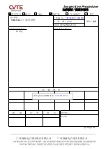
Page 8: ...THIS DOCUMENT AND BUSINESS SECRETS CONTAINED HEREIN ARE PROPERTY OF OUR COMPANY NO DUPLICATION IS ALLOWED WITHOUT PRIOR APPROVAL Inspection Procedure SIS512 TB QE17 0009 A 0 11 SIS512 QR ZZQM 001 BPM...

Page 9: ...menu key and follow with key 1 1 4 7 one by one 1 TCL Factory AT Initialize the TV and enter P mode preset factory channel table 2 Shop Mode Init Initialize the TV and exit P mode 3 AGING MODE Go to...

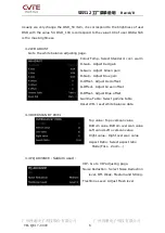
Page 10: ...ADC B Offset Adjust 6 PICTURE To change Parameters about picture SOURCE Select source Picture Mode To change Parameters for different picture mode 4 1 PICTURE CURVE Curve Typr Select Bringhtness Cont...

Page 11: ...een gain B Gain Adjust Blue gain R Offset Adjust Red offset G Offset Adjust Green offset B Offset Adjust Blue offset Gamma Table Select gamma table Reset WB reset white balance data 4 3 OVERSCAN BY PI...

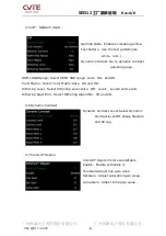
Page 12: ...ix Select Color Matrix Auto SD and HD Dithering Level Select Dithering Level Auto Off Level1 Level2 and Level3 Dithering Algorithm Select Dithering Algorithm 3D and 2D 4 6 Dynamic Contrast Dynamic Con...

Page 13: ...in decoder LDLY Adjust LDLY in decoder Filter Select Filter 4 9 PC Preset Auto Adjust Do auto adjust in PC mode H Position Adjust Horizontal position V Position Adjust vertical position Phase Adjust p...

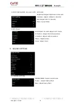
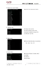
Page 14: ...3 VOLUME CURVE Vol Curve 1 100 Adjust speaker volume gain Volume Curve HP Adjust headphone volume gain 5 4 PRESCALE LINTOUT Input Vol Spk Offset Go to Input Vol Spk Offset adjusting page Input Vol Li...

Page 15: ...urce 5 7 POWER LIMIT PLC Power limit control Sp Attack Speaker output limit Hp Attack Headphone output limit Lo Attack AV out limit 5 8 EQ Setting EQ Mode Select EQ mode include Rock Pop Jazz user off...

Page 16: ...x 2600mA Current Max 50mA Current Max 1525mA Current Max 280mA Current Max 460mA 12V_AMP AMP UT3 BLOCK DIAGRAM S2 TUNER 13V 18V 500mA UZ1 LNB_PW DCDC 1 2A 220mA 110mA S2T512 LVDS 8bit AMP MUTE Audio o...

Page 17: ...110 DB111 L N RB102 RB145 3 1 N L CNB1 DB102 RB130 NTCB1 RB161 RB162 RB163 RB164 RB125 RB126 RB124 RB127 RB152 RB151 A K DB120 CB120 CB118 DB103 VBL RB153 1 1 3 3 2 2 ZB103 1 1 3 3 2 2 ZB104 DB803 DB8...

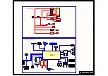
Page 18: ...1702 COCD17 PICD1801 PICD1802 COCD18 PICD1901 PICD1902 COCD19 PICD2001 PICD2002 COCD20 PICD2101 PICD2102 COCD21 PICD2201 PICD2202 COCD22 PICD2301 PICD2302 COCD23 PICD2401 PICD2402 COCD24 PICD2501 PICD...

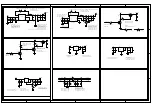
Page 19: ...06 COCN18 PICN2401 PICN2402 PICN2403 PICN2404 PICN2405 PICN2406 PICN2407 PICN2408 PICN2409 PICN24010 PICN24011 PICN24012 PICN24013 PICN24014 PICN24015 PICN24016 PICN24017 COCN24 PICS101 PICS102 COCS1...

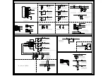
Page 20: ...H802 COCH8 PICH901 PICH902 COCH9 PICH1401 PICH1402 COCH14 PICH1601 PICH1602 COCH16 PICH1801 PICH1802 COCH18 PICH2101 PICH2102 COCH21 PICN101 PICN102 PICN103 PICN104 PICN105 PICN106 PICN107 PICN108 PIC...

Page 21: ...CNF2019 PICNF2020 PICNF2021 PICNF2022 PICNF2023 PICNF2024 PICNF2025 PICNF2026 PICNF2027 PICNF2028 PICNF2029 PICNF2030 PICNF2031 PICNF2032 COCNF2 PICNF301 PICNF302 PICNF303 PICNF304 PICNF305 PICNF306 P...

Page 22: ...R 20 6 3V C35 1uF 0402 X5R 20 6 3V PIC3401 PIC3402COC34 PIC3501 PIC3502 COC35 PIC3601 PIC3602COC36 PIC3701 PIC3702 COC37 PIC3801 PIC3802 COC38 PIC4001 PIC4002 COC40 PIC4101 PIC4102 COC41 PIC4201 PIC42...

Page 23: ...COCA14 PICA1501 PICA1502 COCA15 PICA1601 PICA1602 COCA16 PICA1701 PICA1702 COCA17 PICA1801 PICA1802 COCA18 PICA1901 PICA1902 COCA19 PICA2001 PICA2002 COCA20 PICA2101 PICA2102 COCA21 PICA2201 PICA2202...

Page 24: ...OCT13 PICT1401 PICT1402 COCT14 PICT1501 PICT1502 COCT15 PICT1601 PICT1602 COCT16 PICT1801 PICT1802 COCT18 PICT1901 PICT1902 COCT19 PICT2001 PICT2002 COCT20 PICT2101 PICT2102 COCT21 PICT2201 PICT2202 C...

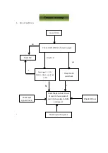
Page 25: ...IIC bus Check the peripheral circuit of mail IC check solder of main IC check data fo NVM and reset it Check reset signal of main no switch on Check 3 3V 12V 24V of power supply Check PW Check DC DC p...

Page 26: ...IC check LVDS cable Check crystal frequence Check the peripheral circuit of mail IC updating SW reset NVM replace main IC Abnormal picture All signal source bad Individual signal source bad Check the...

Page 27: ...e function Abnormal sound Check all sound source Individual sound signal source Check the sound signal link to main IC Check the peripheral circuit of main IC SW Check the power of sound IC Check soun...

Page 28: ......

Reviews: