background image

MODIFIERS  

Alpha Mod.

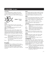
The Alpha  Mod. settings

The settings of the Alpha Mod. are located in the Mod, Modifiers
page. Select Alpha Mod. and press Enter.

Mode

Sets whether the Alpha Mod. should have a range of +/- 100 or
0-100.

Response

Sets whether the Alpha Mod. bounces back to 0 (called
“Bounce”) after it’s been dialed or stay steady at the value dialed
in (called “Steady”).

Delay

Sets the amount of time before the Alpha Mod. starts bouncing
back to 0.

Time

Sets the Bounce time, i.e. how long should it takes the Alpha
Mod. to bounce back to 0.

Midway

Makes it possible to change the bounce curve by changing the
Midway value.

Slope

Changes the slope of the bounce curve.
This delay is only active when the “Response” parameter is set to
“Bounce”.
All Alpha Mod. settings are stored with the Preset.

Controlling Alpha  Mod. externally

The Alpha Mod. external controller is set up in the I/O Setup,
CTRL page. This controller is used to both send and receive
control values to and from the Alpha Mod., e.g. if the Alpha Mod.
is set up to be controlled by MIDI controller #7, the movements
of the Alpha Mod. will be sent out on that controller as well.  

The Alpha  Mod. wheel

The Alpha Mod. wheel can be used as a realtime modifier and
has several setup possibilities. The Alpha Mod. can be connected
to several parameters simultanuously. It can be controlled
externally or work as an external controller for other devices by
sending out control information via MIDI. The LED bar above
the Alpha Mod. shows the current position of the wheel. The
exact setting and connections of the Alpha Mod. wheel is
displayed in the Alpha Mod. display.

The Alpha  Mod. display

Press the Alpha Mod. key on the frontpanel of the FireworX to
access the Alpha Mod. display. 
The display gives you an overview of the parameters controlled
by the Alpha Mod. wheel. Use the Parameter wheel to scroll
through the controlled parameters and press the Enter key for fast
access to the Link display of the current parameter.
Press Exit to return to the Alpha Mod. display.
Note that the parameter values displayed are the output values of
the link display.

Connecting the Alpha Mod.

Press the Mod key and select the Modifier Matrix page by using
the < > Arrow keys.
The Alpha Mod. is the first Modifier entry to the far left in the
top bar. Dial the Parameter wheel to select the parameter to be
controlled and dial the value wheel one click clock wise to select
the Alpha Mod. wheel. 

38

Parameteres controlled

by Alpha Mod.

Press Enter to hyper

jump to Link display

Alpha Mod. position

The Alpha Mod. page

Summary of Contents for FirewarX

Page 1: ...FireworX STUDIO EFFECTS PROCESSOR USERS MANUAL ...

Page 2: ......

Page 3: ...quipment should be installed near the socket outlet and disconnection of the device should be easily accessible To completely disconnect from AC mains disconnect the power supply cord from the AC receptable The mains plug of the power supply shall remain readily operable Do not install in a confined space Do not open the unit risk of electric shock inside Caution You are cautioned that any change ...

Page 4: ...uant to part 15 of the FCC rules These limits are designed to provide reasonable protection against harmful interference in residential installations This equipment generates uses and can radiate radio frequency energy and if not installed and used in accordance with the instructions may cause harmful interference to radio communications However there is no guarantee that interference will not occ...

Page 5: ...age p 27 Layout Exercises p 28 MODIFIERS PAGE 29 MOD P 29 Modifier display p 29 The flow of the Modifiers p 29 Matrix page p 29 Link page p 31 Dials page p 31 Modifier Exercises p 32 Modifiers page p 33 External loop p 37 Alpha Mod p 38 Tempo p 39 Insert loop p 40 SYSTEM AND MIDI PAGE 41 I O SETUP P 41 I O Setup display p 41 Signal page p 42 Level page p 43 MIDI page p 43 External Controllers p 44...

Page 6: ...ith 24 bit AD DA converters AES EBU S PDIF Toslink and ADAT interfaces About this Manual Many people in the music business and elsewhere have an aversion to reading manuals We understand that So if you feel like starting without reading the whole manual simply get going You can always use the manual for checking out areas that you have questions about or if you want to dig deeper into the unit Ref...

Page 7: ... including Ring Modulator Digital Cruncher Sweeping Filters Formant Filters Chaos Noise generation and many more Nine external and eleven internal Modifiers that can be tied to numerous parameters Up to twenty connections can be made simultaneously Each connection s Modifier relationship can be transformed All nine External Modifiers can be controlled via MIDI controllers Velocity Pitchbend Aftert...

Page 8: ... gain reduction of one of the Dynamics blocks LED s The three LED s indicate MIDI activity Preset Edited and Digital lock The Digital Lock LED blinking indicates lack of external clock POWER Press and hold the Power switch for about 3 seconds then release to power off IN OUT KNOBS The overall analog Input level is adjusted via the knob in the upper left corner of the FireworX The Input should aver...

Page 9: ...onfirm The Exit key is used to exit a menu or to cancel an action 7 INTRODUCTION The Front Panel EFFECT MUTE The twelve effect keys are dedicated to mute bypass any of the twelve effect blocks These keys can mute bypass an effect block at any time no matter what display you are working in When you are in the Effects Edit display double click for fast access to the Edit parameter menu ALPHA MOD The...

Page 10: ...ES standards External control jack can use momentary alternating and continuous type pedals The FireworX power supply is capable of operating at any line voltage from 100 240 Volts 50 60Hz INTRODUCTION The Rear Panel 8 Cables Sleeve Pin 1 Ground Tip Pin 2 Hot Ring Pin 3 Cold Pin 1 Pin 1 Ground Pin 2 Pin 2 Hot Pin 3 Pin 3 Cold Sleeve Pin 1 Ground Tip Pin 2 Hot Sleeve Pin 3 Cold XLR XLR Jack unbalan...

Page 11: ...alanced Input Gain Channel select ADAT OPTICAL Channel select ADAT OPTICAL Con Pro Levels Con Pro Levels Input Selector Bypass Output Gain Digital Output Analog Outputs balanced INTRODCUTION The Signal Flow 9 Modifier Flow Digital Input Gain Digital Output Gain Input Output ...

Page 12: ...open to be used as Vocoder or Ring Modulator Carrier input Group insert Connect the left right insert send from your subgroups to the FireworX left right input Connect the FireworX left right outputs to the subgroups insert return This setup makes it possible to mix several sources through the FireworX and a master or group effect to the sources Insert External Device When using the Analog In Outs...

Page 13: ... Edit and press Enter Press Exit to leave the Edit display Routing Changing the order of the effect blocks is done in the Routing display Press the Effects key and select the Routing display using the Arrow keys Place the cursor where you want to insert an effect block double click the mute key of the block you want to insert and dial the Value wheel to select the right sub algorithm sub algorithm...

Page 14: ...ers 1 8 Master Volume Global Tempo Overall Bypass Effects block bypass Level page Sets Digital In Out levels and displays Analog In Out levels Signal page Sets Input source Insert loop I O Sample rate ADAT channels Displays incoming sample rate I O SETUP Matrix page Connects External and Internal Modifiers to effects parameters Modifiers page Sets up Internal Modifiers parameters Dials page Simula...

Page 15: ...or Preset number Preset page selected The Preset page containing the block Reverb The List Page The List page shows the FireworX presets on a continuous list starting with the 200 Factory Presets marked F followed by the User Presets marked U and last but not least the optional Card Presets marked C Dial the Parameter wheel to scroll through the list and press Enter to recall Recalling a preset Wh...

Page 16: ...lled Press the Enter key to Recall the Preset Exercise 2 How to search for Presets containing a specific effect Press the Recall key Press the Enter key to Recall the Preset Exercise 2 How to search for Presets containing a specific effect Now we will try to recall a Preset containing a specific effect in this exercise a delay Select the Filter parameter by using the Parameter wheel Dial the Value...

Page 17: ...space indicator The Free space indicator tells you how much room there is left in the FireworX internal RAM bank The FireworX can hold a maximum of 200 User Presets however the actual number depends on the size of your Presets and may be less than 200 This is due to the dynamic Preset memory structure of the FireworX The Name Page In the Name page you can change the name of your Preset and change ...

Page 18: ...card Preset copy to or from card is done in the Utility Card page see Utility for further description Card types S RAM Type 1 PCMCIA cards with a minimum of 64Kbytes maximum of 2Mbytes S RAM The Store page The Name page The Storing space The Name of the Preset Free space indicator The New name of the Preset The function of the Alpha Mod Select CAP for capital letters or press the Exit key to toggl...

Page 19: ...built from Press the Store key to access the Store display Use the Arrow keys to select the Name page Now use the Parameter wheel to move the cursor in the name the Value wheel to select a letter in the Letterbox and press Enter to insert the chosen letter In order to change the Alpha Mod function text dial the Parameter wheel until the cursor jumps to the next line The new name has to be stored w...

Page 20: ...rcise will describe how to delete a single Preset The FireworX also has the ability to clear the whole User Preset bank instantly please see the Reset page for further instructions Press the Store key to access the Store display Use the Arrow right key to select the Delete page Dial the Value wheel to select the Preset you want to delete Press Enter to confirm the deleting of the current Preset Wa...

Page 21: ...ine displays the sub algorithm running in the current highlighted block The second way is to double click the key of the block you want to edit In case you have more than one of a specific block the first double click will take you into the block 1 the second double click will take you into 2 and so forth After entering the last block the double click will take you back to 1 Example The FireworX i...

Page 22: ...play Use the Parameter wheel to change the cursor position and the Value wheel to change values In case the Preset contains more than one of the blocks you want to edit a second double click on the block Mute key will take you into number two Exercise 6 How to Edit an effect block Press the Effects key Use the Arrow keys to select the Edit display Dial Parameter wheel to move the cursor Dial Value...

Page 23: ...e Mute mode of each block The full Routing grid can be up to 8 by 8 spaces and you can place any effect anywhere in the grid however the FireworX will not scroll through the last row unless a block is placed closer than two rows away The size of the grid can be changed in the Layout page Maximum number of inserted blocks Due to the dynamic processing power structure of the FireworX you can keep ad...

Page 24: ...cause serious changes in the sound due to phase cancellation Feedback The Feedback block can feed the sound back from one point to another in the signal chain Place the Send block where you want to tap the sound and place the Return block where you want the sound to re enter the signal chain Warning The Feedback can cause serious overloads in the Routing Parallel or Serial The Effects blocks of th...

Page 25: ... algorithm where you are able to set different delay times in left and right channels remember to set the panning of the two delay taps Exercise 7 Inserting an Effect There are two ways of inserting an effect Let s start by setting up a Phaser and after that a Delay Press the Effects key if you are not already there Use the Arrow keys to select the Routing page Use the Parameter wheel to place the...

Page 26: ...he settings of the block are still being remembered Move the cursor to position 1 2 using the Value wheel Double click the Delay Mute key on the front panel Dial the Value wheel until you see Delay 1 Dual in the lower text line Press Enter to confirm Now the Delay block is in a parallel position as opposed to the Phaser from exercise 7 8 Exercise 9 Moving an existing block Select the Routing page ...

Page 27: ... if the FireworX is set to Effect mute Off in the Utility Config page see Recall Recall Mode for further description Here is the description of what the five modes will do when the front panel mute key is pressed Mix 0 Will set the Mix parameter in the Edit Parameter page to 0 Set direct signal level up to 100 FX Out Will mute the output of the effect and preserve direct signal level according to ...

Page 28: ...se insert a Synth block in a Routing See exercise 7 Press the Effects key and use the Arrow keys to select the Routing display Place the cursor on the Synth block Press Enter Select Out L by using the Parameter wheel Select Dry by using the Value wheel Select Out R by using the Parameter wheel Select Wet by using the Value wheel Now the block is set up to only pass direct signal to the left output...

Page 29: ... carry out the selected function The Tool page The Tool page offers a number of different readouts and shortcuts to parameters that can be used in the Edit page on each block Select the information function that you desire using the Parameter wheel and press Enter to confirm The Tools can be bypassed in the Edit page by pressing the Exit key In Meter Mix Will show the Input level in each block and...

Page 30: ...f No output line indicates that the block is using the Off setting on the current output Mute Effect Makes it possible to bypass each block individually using the Value wheel This can be very useful when more than one of a certain block is inserted in the Routing Place the cursor on the block you want to mute using the Parameter wheel and turn the Value wheel Copy effect from Preset This feature e...

Page 31: ...erful tool for setting up modulation connections for External or Internal Modifiers The Modifiers page contains setups of all Internal Modifiers The Dials page is used for simulating External Modifiers The flow of the Modifiers The FireworX has nine external Modifiers the Alpha Mod and Ext 1 8 These Modifiers can be controlled by MIDI Controllers Aftertouch Note On Off Pitch Bend MIDI Program Chan...

Page 32: ...Set middle value Set highest value Change curve Set reaction time Dial Parameter wheel to move Ext Modifier 1 Press Enter and dial Value to change Ext Modifier press Exit to simulate Dial Value wheel to move Ext Modifier 2 Selected Selected Transformation MODIFIERS Modifier 30 The Matrix page The Link page The Dials page ...

Page 33: ... Modifier is in minimum position Mid input Sets the value that the controlled parameter will have when the Modifier is in middle position High input Sets the value that the controlled parameter will have when the Modifier is in maximum position NOTE These same parameters also apply to the other modulation sources for example Envelope Low when the input signal into the FireworX is at its lowest and...

Page 34: ... page Dial Parameter wheel until the cursor points to the parameter to be controlled Dial Value wheel to choose Modifier Exercise 13 How to use the Link display This exercise gives an example on how the Link display can be used to adapt a Modifier connection We will set up a Ducking delay Select any Preset containing a Delay Enter the Modifier Matrix page Connect the Delay Mix parameter to ENV det...

Page 35: ...cribed on page 39 Pitch detector The Pitch detector senses the pitch of the incoming source signal and converts it to control information that can be used to control the parameters of the Modifier Matrix To achieve maximum performance the input source should be monophonic and the detection range should be limited to the area where the source is present NOTE The Pitch detector takes up 4 of process...

Page 36: ...tra gate ADSR 1 2 ADSR is an abbreviation of Attack Decay Sustain Release ADSRs are used to play short control signal sequences triggered by the audio input You set up a number of terms to describe the curve of the control signal and a trigger level also known as Threshold Attack The Attack or rise time of the curve i e how long it takes the control signal to go from minimum to maximum value i e 0...

Page 37: ...amout of time set by the Speed parameter E g if Speed is set to 1Hz the defined number of samples will be played back once every second Tempo Sets the Freeforms relationship to the global tempo The defined number of samples will played back during the value set by Tempo Example If Freeform is set to 8 samples and Tempo is set to 4 1 4 bars you will hear two samples in each bar Depth Sets the maxim...

Page 38: ...o 1 Note to Synth Freq The Note to Synth Type converts control values to notes This can be used to convert Pitch detector or MIDI note information to Synth control information Feed 2 is used for Pitch Bender control Example 1 Connect the Pitch detectors output to Function 1 Feed 1 in the Modifier Matrix Connect the output of the Function to the input of the Freq parameter of the Synth Curve genera...

Page 39: ...n to the input of a Freq parameter of the Filter Resonator or Resochord The Resonator will now follow the pitch of the incoming source material Example 2 Set up Ext 1 to be controlled by MIDI Note On key Connect the output of Ext 1 to Function 1 Feed 1 Connect the output of the Function to the input of a Freq parameter of the Filter Resonator or Resochord The Resonator can now be controlled by an ...

Page 40: ...n be used as a realtime modifier and has several setup possibilities The Alpha Mod can be connected to several parameters simultanuously It can be controlled externally or work as an external controller for other devices by sending out control information via MIDI The LED bar above the Alpha Mod shows the current position of the wheel The exact setting and connections of the Alpha Mod wheel is dis...

Page 41: ...tick on until you press the Tempo key again or it can disappear automatically Choose whether the Tempo should be Sticky or not in the Utility page The Tempo display will read out the tapped BPM Beats per minute and the tapped time in milliseconds If you prefer to dial the BPM simply place the cursor on BPM parameter and dial the Value wheel to change the Tempo The FireworX is also capable of follo...

Page 42: ...ound the External loop not both Here is a couple of setup examples on how to avoid phase cancelation Example 1 The External loop contains a Reverb set to 100 effect an additive effect All of the Dry signal must now be passing around the External loop no Dry signal should be coming through the External loop The Mix parameter of the External loop can be set anywhere between 0 and 100 in the Return b...

Page 43: ...he Block Mute keys etc The Level page contains the Analog the Digital In Out level and displays the incoming sample rate when using external clock The Signal page contains the source select of the FireworX Input and Outputs including the External Loop and Dither All settings of the I O Setup are global i e they do not change with the Presets SYSTEM MIDI I O Setup The Signal page The Level page Sig...

Page 44: ...o the incoming clock NOTE The six unprocessed channels are not passed through the FireworX Ch Channel The Channel parameter selects which channels the FireworX are using for Input The four possibilities are Left input only L Right input only R Left and Right summed to Mono L R Stereo STE Insert The Insert loop is a unique feature that makes it possible to insert an external device into the Routing...

Page 45: ...n the Control page Basic Channel The basic MIDI channel of the FireworX This is the channel that you should transmit Program changes on to change Presets in the FireworX The FireworX outputs the on off status of the blocks at Preset change NOTE The FireworX s Modifiers and block on off are configured separately meaning that they may be transmitting on MIDI channels different from the Basic channel...

Page 46: ...easy for you to set up an External controller we designed a Learn function Place the cursor on the parameter you want to control press Enter to activate Learn and move your External controller The FireworX will now automatically detect the incoming controller no matter if it is connected to MIDI or to the pedal jack In each of the following parameters you can setup the input that the current param...

Page 47: ...fier Matrix The controller set up as to control the Alpha Mod externally is also used for transmitting the Alpha Mod movements This makes it possible to record the modulations of the Alpha Mod Ext 1 8 These eight inputs can control numerous parameters in the algorithms Their functions are set up in the Modifier Matrix page Press the Enter key and move the External controller for auto detection Eff...

Page 48: ... The current number is included in the protection Protect High limit Sets the higher limit of the Preset protect The current number is included in the protection MIDI Bulk Dump You can backup the User Presets of the FireworX to another FireworX or to MIDI recording device using these functions User Bank to MIDI Connect your FireworX s MIDI Out to another FireworX a sequencer or any other MIDI reco...

Page 49: ...k Preset start at 5 because you want the first copied Presetto start at 5 the Number of Presets to 5 because that is the number of Presets you want to copy Now select Copy From User Bank to Card scroll to Execute copy and press Enter twice to confirm the copy operation User Bank Preset start This parameter determines where the copy action should start in the internal User Bank Card Bank Preset sta...

Page 50: ...s changes in the sound due to phase cancellation Feedback The Feedback block can feed the sound back from one point to another in the signal chain Place the Send block where you want to tap the sound and place the Return block where you want the sound to re enter the signal chain In the Feedback Return block you will find the following parameters FB level Sets the amount of level returned into Rou...

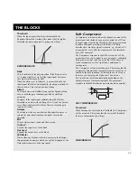
Page 51: ...k is present in the Routing this parameter determines which one will be displayed by the Gain reduction meter on the front panel Soft Compressor A Compressor is meant to reduce the dynamic content of the input signal and thereby keep a more constant level When the input signal exceeds the threshold the Compressor starts to reduce the signal according to the Ratio The Ratio describes how much the s...

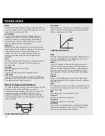
Page 52: ...ter responds to the peak level whereas the Compressor responds to the RMS average level Peak compression in general is a bit more aggressive sounding The parameters available in the Modifier Matrix are marked with an asterisk HARD COMPRESSOR LIMITER Threshold When the input level exceeds the Threshold the Compressor will be activated This means that the lower the Threshold the more compression you...

Page 53: ... resonate more than 2nd order filters Locut Freq Sets the frequency of the Locut Resonance filter Range 20Hz 5kHz Hicut Freq Sets the frequency of the Hicut Resonance filter Range 150Hz 15kHz Lo Resonance Sets the amount of Resonance on the Locut filter Hi Resonance Sets the amount of Resonance on the Hicut filter Connect an LFO or an expression pedal to the two frequency parameters using the Modi...

Page 54: ...if you set it to 1 4T you will get quarter note triplets of the tapped tempo 1 4 equals the BPM tapped Tempo The subdivisions available are 16 1 16 bars for performing one period 8 1 4 1 2 1 1 1 and 1 2 1 32 in straight dotted and triplet notes 1 4 equals BPM beats per minute If you select Ignored the current parameter will use the Preset value and will not be affected by the Global Tempo Depth Ad...

Page 55: ...Level Controls the output level of the block THE BLOCKS NOTE The peak of the filters can get very loud and can easily hit the internal ceiling and thereby cause distortion To prevent that turn down the input level of the Filter block Resochord The Resochord is based on the same algorithm as the Resonator However in the Resochord the four resonators are scaled within chords All you have to do is ch...

Page 56: ...le in the Modifier Matrix are marked with an asterisk DISTORTION filter is relative to the Frequency of the corresponding Resonator voice The slope of the filter is 12dB octave Range 0 100 Levels Voice 1 4 Sets the level of each of the four resonators Panning Voice 1 4 Sets the panning of each of the four resonators Mix Mixes between direct sound and effect In Level Controls the input level of the...

Page 57: ...common in the early days of the digital world In the FireworX this artifact is magified into an effect Sound wise the Aliasing appears as an unharmonic fairly high frequency distortion The Quantizer produces an artificial noise floor as if the signal had been sampled at a lower bit resolution The parameters available in the Modifier Matrix are marked with an asterisk CRUNCHER Aliaser Factor Sets t...

Page 58: ...fty fifty mix of the upper and lower sideband equals the sound of a traditional ring modulator Note that the dynamic range of the sideband outputs is the sum of the dynamic ranges of the two inputs so compression of one or both inputs is recommended This can be done by using the build in Carrier AGC Automatic Gain Control The parameters available in the Modifier Matrix are marked with an asterisk ...

Page 59: ...rols the output level of the Ring Modulator block Ring Mod Internal This variation of the FireworX Ring Modulator provides an internal carrier sine wave generator with user controllable frequency That means that the left and right input of the block is summed together and used as control input The parameters available in the Modifier Matrix are marked with an asterisk RING MOD INTERNAL Carrier Set...

Page 60: ...d use this block as a mini synthesizer See Modifiers Functions for further details Curve Selects the curve being generated Choose between Square Sine Triangle and Sawtooth Square PW Controls the division of the upper and lower part of the Square waveform e g if Pulsewidth is set to 75 the upper half of the waveform will be on for 75 of the time Locut Cuts off frequencies lower than the selected fr...

Page 61: ...er of blocks 1 Processing power 17 20 per block The Pitch block contains two different sub algorithms Single Voice and Dual Voice The parameters available in the Modifier Matrix are marked with an asterisk Single Dual Voice Pitch PITCH Pitch 1 2 Sets the amount of Pitch on each of the two voices in cents Maximum pitch is 2400 cents Delay 1 2 Sets the Delay of each of the two voices Maximum delay t...

Page 62: ...inute If you select Ignored the current parameter will use the Preset value and will not be affected by the Global Tempo Depth Adjusts the modulation depth of the Chorus also known as Intensity Mix Mixes between direct sound and effect In Level Controls the input level of the block Create a Vibrato by setting the Mix at 100 Depth at 5 10 and Speed to 1 2Hz Advanced Chorus Advanced Chorus adds some...

Page 63: ...l control over the Flanger Speed lets the Flangers internal LFO handle the modulation Speed The modulation speed of the Flanger also known as Rate Tempo The Tempo parameter sets the relationship to the global Tempo e g if you set it to 1 4T the Flanger will use a quarter note triplet of the tapped tempo to perform one cycle 1 4 equals the BPM tapped Tempo The subdivisions available are 16 1 16 bar...

Page 64: ...Note that the Cross feed can be negative i e Cross feed in reversed phase LFO Curve Sets the curve of the LFO Choose between Sine or Triangle The most commonly used waveform in Flanging is Sine See Curve figures in Tremolo LFO Phase An LFO phase change causes a small delay in one of the waveform starting points This means that left and right outputs start the current waveform at two different poin...

Page 65: ...e Modifier Matrix are marked with an asterisk DUAL DELAY Time 1 Sets the delay time of the first Delay tap Maximum delay time is 675 ms Time 2 Sets the delay time of the second Delay tap Maximum delay time is 675 ms Tempo The Tempo parameter sets the relationship to the global Tempo e g if you set it to 1 4T the Delay will use quarter note triplet of the tapped tempo to perform one cycle 1 4 equal...

Page 66: ...f the two Delay taps Lowcut 1 2 3 Cuts off frequencies lower than the selected frequency The slope of the filter is 12dB octave Highcut 1 2 3 Cuts off frequencies higher than the selected frequency So if you feel that there is too much treble in your signal you can remove it by adjusting the highcut filter down The slope of the filter is 12dB octave Line Level 1 2 Adjusts the input level of the tw...

Page 67: ... the highcut filter down The slope of the filter is 12dB octave Lowcut Cuts off frequencies lower than the selected The slope of the filter is 12dB octave Highcut Cuts off frequencies higher than the selected frequency So if you feel that there is too much treble in your signal you can remove it by adjusting the highcut filter down The slope of the filter is 12dB octave Mix Mixes between direct so...

Page 68: ...r part of a natural reverb which is experienced as prolonging the sound and creating some depth behind the source or direct signal but integrating it in the spatial characteristics of the hall or room like you experience in natural ambience or reverb By emulating initial room reflections the FireworX can create some very deep and wide stereo images placing the source or direct signal in the hall r...

Page 69: ...o it is linked to High color Auto Wool Warm Real Clear Bright Crisp Glass Color Factor Emphasizes or reduces the character set by Color Range 50 Predelay Allows adjustment of the predelay the time until the first reflection appears which is automatically set when choosing the Room size Range 50 Decay Level Adjusts the level of the Decay which is master controlled by the reverb level With this cont...

Page 70: ...ins five sub algorithms Simple Tremolo Advanced Tremolo Simple Panner Surround Panner and Stereo Enhance A Panner is basically a change of the level opposite in Left and Right channels An LFO is connected to these levels and turns them up and down A Tremolo is also a change of level controlled by an LFO except the level change in Left and Right channels are identical So the basic difference betwee...

Page 71: ...e signal while panning The parameters available in the Modifier Matrix are marked with an asterisk PAN TREMOLO Mod Link Only in Simple Panner Enables you to bypass the internal LFO of the Panner and control the sweep manually through the Modifier Matrix When set to Shape the Speed entrance in the Modifier Matrix works as manual control over the Panner Speed lets the Panner s internal LFO handle th...

Page 72: ...cessing power 19 22 per block The EQ block contains two different sub algorithms Fixed five band parametric EQ and modulatable four band parametric EQ Both of these EQs are true stereo Fixed parametric The parametric EQ contains two shelving filters 1 and 5 and three bell filters 2 3 4 A low shelving filter is a filter that works from a certain target frequency on down meaning everything below the...

Page 73: ...ith an asterisk MODULATABLE EQ Freq 1 4 Use the freq parameter to set the target frequency of the current band BW bandwidth 1 4 Bandwidth adjusts how broad the bell filters are Gain 1 4 Use the gain to boost or cut the target frequency All filters can boost or cut 12dB Mix Mix between direct sound and effect In Level Controls the input level of the block Out Level Controls the output level of the ...

Page 74: ...eaning all parameter settings of Utility I O Setup except analog in out levels Tempo Alpha Mod Load setup from card Insert the pc card containing your FireworX setup Press Enter twice to confirm that you want to load this setup All system parameters will be reset according to the saved setup meaning all parameter settings of Utility I O Setup except analog in out levels Tempo Alpha Mod Reset Syste...

Page 75: ...nter Connect AES EBU output to AES EBU input Connect S PDIF output to S PDIF input Connect ADAT output to ADAT input PPM must show 0dB to pass test Press Exit to leave Digital I O test Midi I O test Select MIDI I O test by pressing Enter Connect MIDI Out to MIDI In Prg change 1 128 is sent out on MIDI Thru Connect this socket to a MIDI compatible device and confirm the Prg changes Press Exit to le...

Page 76: ... is phasing with your direct signal You are running the FireworX in a parallel setup but the Mix function in I O Setup Signal menu is set to Wet The Insert loop is causing phase cancellation See Insert loop for further explanation Right input meter is not showing any signal You selected L in the source parameter in I O Setup signal page Effects only in the Left Output You are only using Left input...

Page 77: ...X X Altered Note Number X 1 127 True Voice X 1 127 Velocity Note ON X O Note OFF X O After Touch Key s X X Ch s O O Pitch Bend O O Control Change 0 119 0 119 Prog Change O O True 0 127 0 127 System Exclusive O Bulkdump O Bulkdump Common Song Pos X X Song Sel X X Tune X X System real time Clock X O Commands X X Aux Messages Local ON OFF X X All Notes OFF X O Active Sense X X Reset X O Notes O YES X...

Page 78: ...kHz 6 dBFS FS 16 dBu 10 Hz to 20 kHz 0 0 2 dB 80 dB 10 Hz to 20 kHz typical 100 dB 1 kHz XLR balanced pin 2 hot 100 ohm active transformer 22 dBu balanced 10 dBu to 22 dBu 24 bit 1 bit 128 times oversampling x 0 57 ms 48 kHz 100 dB unweighted 104 dB A 86 dB 0 005 1 kHz 6 dBFS FS 16 dBu 10 Hz to 20 kHz 0 0 5 dB 60 dB 10 Hz to 20 kHz typical 90 dB 1 kHz XLR AES EBU RCA Phono SPDIF Optical Toslink AD...

Page 79: ...3 24 25 26 27 28 29 30 31 32 33 34 35 36 37 38 39 40 41 42 43 44 45 46 47 48 49 50 Factory Presets Nr Name Description PRESETS Very ugly guitar sound Ring modulator combined with a slap back delay Ring modulator combined with a Resonance filter Ring modulator and delay Mod Wheel creates endless feedback Vocoder and Synth convertes anything into percussive sounds Delay Reverb and Flanger turned int...

Page 80: ...140 141 142 143 144 145 146 147 148 149 150 Nr Name Description Phaser Ring Modulator and Pitcher Turn up the Panner speed with the Mod Wheel Advanced panner thing with Pitch Phaser Chorus and Delay Bubble sounding preset Freeform modifier controlling the Delay plus more Hear the frogs Funny preset with Distortion on the Mod Wheel Hear the sound drive by Mars mens invades your material Don t use t...

Page 81: ...47 248 249 250 Factory Presets Nr Name Description PRESETS EQ More Electrosqueeze Diffusion Grating Feedback Octave Get Mean 151 Rum Dullais Dt Modsquad Animation Tuning Filtered Source Pitch Freeze Frequency Reduce Delays Pitch Tune Me Now Depth Charge Add Him Dt Sun Through Clouds Adds Tremolo Brightnessness Soft On Left Or Right Low On Left Or Right Trigger Echo Lvl Image Stereo2mono Resonance ...

Page 82: ...337 338 339 340 341 342 343 344 345 346 347 348 349 350 Nr Name Description Less Cheese In A Can Oxygen Content Bright Dark Centers Signal Bring It Close Adds Detune Width Surround Position Alters Mix Image Contour Adjust Positioning Ambience Open The Door And Go Adds Phaser Adds Presence Room Position Change Position Change Position Hi Lo Cut EQ Adjust To The Back Verb Metalness Surround Position...

Reviews: