background image

- 11 -

TC3715 w/Rate Limit

User's Manual

Rev. 2.0 (A0.1)

SHR ID Setting 

(Default IP Setting)

The TC3715s can be connected with a maximum of 128 units.  The IP address can be configured with either
hardware or software (each unit must have a unique IP).  Hardware configuration is limited to the default
IP addresses. Therefore, it is generally used for bench testing.

Note:

 Software configurations will overwrite the hardware settings for IP Address. The reset button can

be used to return the unit to the current hardware settings.

Hardware SHR ID Settings

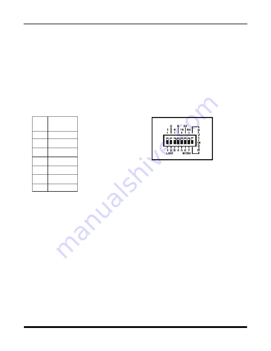
Dip switches 1-7 on the rear panel of the unit are used to configure the TC3715 IP Address. They represent
bit numbers, #1, least significant and #7, most significant. The values(1, 2, 4, 8, 16, 32, and 64) for setting
the IP Address are represented by the bit number exponent of 2 (see table 1 and figure 3). Also refer to
Appendix B.

Chapter 2 - Hardware Configuration

Examples: To set the SHR ID (Default IP Address)

ID=1:

 Set dip switch 1 to the down position and the rest to the up position.

ID=2:

 Set dip switch 2 to the down position and the rest to the up position.

ID=3:

 Set dip switches 1 and 2 to the down position and the rest to the up position.

ID=4:

 Set dip switch 3 to down the position and the rest to the up position.

ID=5:

 Set dip switches 1 and  3 to the down position and the rest to the up position.

ID=6:

 Set dip switches 2 and 3 to the down position and the rest to the up position.

ID=7:

 Set dip switches 1, 2 and 3 to the down position and the rest to the up position.

ID=8:

 Set dip switch 4 to the down position and the rest to the up position.

ID=9 to 127:

  Please refer to the SHR ID Setting Tables on Appendix B.

Note: The SLVE/MSTR Dip switch is Not Used.

When using hardware configurations, the SHR ID = N will set the IP address to 192.168.254.[100+N].

For example, if the unit is set for SHR ID = 12, the IP address is 192.168.254.112.

Table 1.

 SHR ID Setting

Figure 5.

 Rear Panel SHR ID Setting

Dip 

switch #

(Bit #)

Values for 

setting the

SHR ID’s

1       2 =   1

0


2       2 =   2

1


3       2 =   4

2


4       2 =   8

3


5       2 =   16

4


6       2 =   32

5


7       2 =   64

6


Summary of Contents for TC3715

Page 1: ...ecifica tion TC Communications Inc reserves the right to change or modify the contents of this manual at any time without prior notification TC3715 10 100Base T Fiber Optic Switch with Rate Limit Feature Rev A0 1 User s Manual COPYRIGHT 1992 2007 ALL RIGHTS RESERVED MODEL S N DATE TC Communications Inc 17881 Cartwright Road Irvine CA 92614 Tel 949 852 1972 Fax 949 852 1948 Web Site www tccomm com ...

Page 2: ...n 10 Chapter 2 Hardware Configuration 11 SHR ID Setting Default IP Setting 11 Configuring the Alarm Dip Switches Front Panel 12 Chapter 3 Web Configuration 13 Web Based Interface Connection 13 Login Setting 14 IP Setting 15 Port Setting 17 Electrical Port Setting 18 Fiber Port Setting 20 Chapter 4 Serial Telnet Configuration 21 Serial Interface Connection 21 Telnet Interface Connection 22 Chapter ...

Page 3: ...n both fiber ports and RJ 45 ports The incoming data rate on both fiber ports and RJ 45 ports can be limited to 128K 256K 512K 1M 2M 4M 8M 16M 32M and 64M The outgoing data rate on both fiber ports and RJ 45 ports can be limited to 128K 256K 512K 1M 2M 4M and 8M The TC3715 offers two multimode 1300nm or single mode 1300 1550nm optical ports and six Ethernet 10 100Base T Auto Sensing Auto Negotiati...

Page 4: ...e 1310nm Single Mode 9 125µm up to 20 km distance Wavelength 1310nm Single Mode LASER Connector ST FC SC Single Mode 1310nm 75km Model Transmitter FP Laser typical Launch Power 3 to 2dBm 1310nm 9 125µm Receiver PIN Diode typical Sensitivity 36 0 dBm 1310nm 9 125µm Optic saturation level 3 dBm 1310nm 9 125µm Loss Budget 1310nm Single Mode 9 125µm 33dB Distance 1310nm Single Mode 9 125µm up to 75km ...

Page 5: ...wer 8 to 3 dBm 1310nm 1550nm 9 125µm Receiver PIN Diode typical Sensitivity 33 0 dBm 1310nm 1550nm 9 125µm Optic saturation level 3 dBm Loss Budget 1310nm 1550nm Single Mode 9 125µm 29 dB Distance 1310nm 1550nm Single Mode 9 125µm up to 50km distance Wavelength 1310nm 1550nm Single Mode Connector SC Only ...

Page 6: ...ing at half duplex when there is Ethernet Activity LED Status Indicators for Fiber Optic Channels 1 and 2 100M FULL COL Full Duplex Collision Indicator LED LINK ACT when the fiber optic port has established a valid optical link when the optical fibers are not connected Always lit Always lit Solidly lit Off Blinking when Ethernet Activity at the fiber optic port is detected Six RJ 45 10 100Mbps Por...

Page 7: ...itch not used TC Serial DB9 port 9600 8 N 1 9600 Baud 8 data bits no parity 1 stop bit Reset Button Used to reset the unit back to the current hardware settings 1 Unplug the power to the unit 2 Push and hold the Reset Button 3 While holding the button in Plug the power back On then release the button 4 The most will be restored current hardware settings 115 230VAC Power plug Management RJ 45 Port ...

Page 8: ...n in the example below Fiber Optic Cables Fiber Optic Cables Fiber Optic Cables Ma d e inU S A Ma d e in U S A Ma d e inU S A TCCOMM COM TCCOMM COM TCCOMM COM 10 100 INDUSTRIAL ETHERNET FIBER SWITCH 2F 6T 10 100 INDUSTRIAL ETHERNET FIBER SWITCH 2F 6T 10 100 INDUSTRIAL ETHERNET FIBER SWITCH 2F 6T Rx R x R x Tx Tx Tx 100 BASE FX 100BASE FX 100BASE FX F U L L C O L F U L L C O L F U L L C O L 1 0 0 M...

Page 9: ...4 Backbone Using an Extended Star Topology with the TC3715 s Multimode or Single Mode Fiber Optic Cables Made in U S A Mad e in U S A TCCOMM COM TCCOMM COM 10 100 INDUSTRIAL ETHERNET FIBER SWITCH 2F 6T 10 100 INDUSTRIAL ETHERNET FIBER SWITCH 2F 6T Rx Rx Tx Tx 100BASE FX 100 BASE FX FULL COL FU L L CO L 100M 10 0M LIN K A CT LI NK A CT 3 3 2 2 1 1 4 4 5 5 6 6 F 2 F2 F1 F1 Rx R x Tx Tx 100 BASE FX 1...

Page 10: ...ower card installed either on the left or right side of the rack 2 The PWR A or PWR B LEDs on the front panel will light according to which power jack A or B is connected Both LEDs will light when power redundancy is utilized 3 The Vcc1 and Vcc2 LEDs should also light indicating an adequate operating voltage is being derived from the power source 4 Connect the twisted pair cables to the RJ 45 conn...

Page 11: ...he SHR ID Default IP Address ID 1 Set dip switch 1 to the down position and the rest to the up position ID 2 Set dip switch 2 to the down position and the rest to the up position ID 3 Set dip switches 1 and 2 to the down position and the rest to the up position ID 4 Set dip switch 3 to down the position and the rest to the up position ID 5 Set dip switches 1 and 3 to the down position and the rest...

Page 12: ... in the up On position To disable F1 s alarm put the dip switch in the down Off position 4 F2 2X Dip Switch This dip switch enables disables just Fiber Port F2 s alarm To enable F2 s alarm put the dip switch in the up On position To disable F2 s alarm put the dip switch in the down Off position When either fiber port signal is disconnected the TC3715 alarms will be triggered the Alarm LED will fla...

Page 13: ...ess box enter the IP address of the TC3715 For example if the unit is set to factory default enter http 192 168 254 123 5 Once connected you should see the following screen Please refer to the Trouble shooting section if not connected 6 Click the links on the left of the page to navigate to the desired section Figure 7 TC3715 Home Page Note All fields are optional in this page Chapter 3 Web Config...

Page 14: ... user name user Default password password Web Configuration Continue Login Setting You can change the user name and password by clicking on the link Login Setting at the home page Click the browser s Back button to cancel all the changes Click the Apply button to save the changes Figure 8 TC3715 Password Dialog Figure 9 TC3715 Access Setting Page ...

Page 15: ...ur local network administrator for your network settings IP Address Unit s IP Address The default IP Address is 192 168 254 123 If you change the IP Address you must reconnect using the new IP Address Subnet Mask This indicates the TCP IP network class you are using The default Subnet Mask is 255 255 255 0 Gateway IP Address If your connection contains a router enter the IP Address of the Router L...

Page 16: ... the browser s Back button to cancel all the changes Click the Apply button to save the changes and you will see the following screen You need to Reset the unit to apply the new settings 1 By clicking the Reset button Or 2 By resetting the power of the unit Figure 11 TC3715 Reset Page ...

Page 17: ...onfiguration Continue Click the Port Link to configure individual port Click the Refresh button to update the link status Figure 12 TC3715 Port Setting Page Port Setting Click on the Port Setting Link at the home page and you should see the following screen ...

Page 18: ... Port Setting Port State Enable or disable the port Default Enable Speed Duplex Select the Speed and Duplex of the port Auto Negotiate 100M Full 100M Half 10M Full and 10M Half Default Auto Negotiate Ingress Limit Rate limit for data going into the TC3715 port None 128K 256K 512K 1M 2M 4M 8M 16M 32M and 64M bps Default None ...

Page 19: ... Configuration Continue Egress Limit Rate limit for data going out from the TC3715 port None 128K 256K 512K 1M 2M 4M and 8M bps Default None Flow Control Enable or disable the flow control on this port Default Disable Click Apply to apply the new settings ...

Page 20: ...efault Enable Ingress Limit Rate limit for data going in to the TC3715 port None 128K 256K 512K 1M 2M 4M 8M 16M 32M and 64M bps Default None Egress Limit Rate limit for data going out from the TC3715 port None 128K 256K 512K 1M 2M 4M and 8M bps Default None Flow Control Enable or disable the flow control on this port Default Disable Click Apply to apply the new settings ...

Page 21: ... TC3715 DB9 connector using a serial cable 2 Start Hyper Terminal included with Win98 ME 3 Choose the COM port which the serial cable is connected E g Com1 4 Port Settings 38400bps 8 data bit no parity 1 stop bit no flow control 5 Power up the unit and you should see the login screen Figure 15 Hyper Terminal Connection Dialog Figure 16 Port Settings Dialog ...

Page 22: ...C3715 IP address E g 192 168 254 123 4 Set Port to telnet or 23 and set TermType to vt100 5 Once connected you should see the following screen Please refer to the Trouble shooting section if not connected Figure 17 Telnet Connection Dialog Figure 18 Console Login Username and Password for Console login is the same as the Web login Default Username user Default Password password Note Unit will logo...

Page 23: ...e Type Help for all the commands supported by TC3715 Figure 19 Console Help Set This command is used to configure the network settings Please see the next section for more details Logout This command is used to logout from the serial console Reset This command is used to reset the TC3715 ...

Page 24: ... Set Unit s Netmask E g Set netmask 255 255 255 0 Set gateway Set Unit s Gateway IP E g Set gateway 192 168 254 1 Set username Set login username E g Set username john123 Set password Set login password E g Set password 123456 Set default Set unit back to factory default E g Set default IP 192 168 254 123 Subnet Mask 255 255 255 0 Gateway IP 0 0 0 0 Username user Password password Note All set com...

Page 25: ...card 4 Click Properties If your PC has a compatible IP Address and Network Mask Please go to the Web based Interface section Attention Please copy down the existing setting before making any changes Contact your local network administrator if you are unsure about the settings Improper settings may result in disruption of the current network Under the TCP IP Properties Select the Specify an IP addr...

Page 26: ...blem If All LEDs 100M FULL COL and LINK ACT are OFF It means that there is no ethernet electrical signal detected by the TC3715 Check the twisted pair cables for good connectivity Make sure that the units have adequate power Optical Problem If the 100M and FULL COL LEDs are lit and the LINK ACT LED is OFF A Check the physical fiber optic cable connection to make sure it is not loose or broken B Op...

Page 27: ... FULL COL LINK ACT each port Optical Signal Status 100M FULL COL LINK ACT each port Alarm Dry Contact Normal Open Power Source Standard 12VDC 600mA Optional 24VDC 48VDC 125VDC or 115 230VAC with an external power cube Temperature Operating 0o C to 50o C Hi Temp Optional 20o C to 70o C Hardened Temperature Optional 40o C to 85o C Humidity 95 non condensing Physical Standalone Wallmount unit Height ...

Page 28: ...tion may first inspect such goods at the premises of the Buyer or may give written authorization to Buyer to return the goods to TC Communications Inc transportation charges prepaid for examination by TC Communications Inc Buyer shall bear the risk of loss until all goods authorized to be returned are delivered to TC Communications Inc TC Communications Inc shall not be liable for any inspection p...

Page 29: ... Up 11 Down Down Up Down Up Up Up 12 Up Up Down Down Up Up Up 13 Down Up Down Down Up Up Up 14 Up Down Down Down Up Up Up 15 Down Down Down Down Up Up Up 16 Up Up Up Up Down Up Up 17 Down Up Up Up Down Up Up 18 Up Down Up Up Down Up Up 19 Down Down Up Up Down Up Up 20 Up Up Down Up Down Up Up 21 Down Up Down Up Down Up Up 22 Up Down Down Up Down Up Up 23 Down Down Down Up Down Up Up 24 Up Up Up Do...

Page 30: ...Down Up 58 Up Down Up Down Down Down Up 59 Down Down Up Down Down Down Up 60 Up Up Down Down Down Down Up 61 Down Up Down Down Down Down Up 62 Up Down Down Down Down Down Up 63 Down Down Down Down Down Down Up 64 Up Up Up Up Up Up Down 65 Down Up Up Up Up Up Down 66 Up Down Up Up Up Up Down 67 Down Down Up Up Up Up Down 68 Up Up Down Up Up Up Down 69 Down Up Down Up Up Up Down 70 Up Down Down Up U...

Page 31: ...n Up Up Down Down 103 Down Down Down Up Up Down Down 104 Up Up Up Down Up Down Down 105 Down Up Up Down Up Down Down 106 Up Down Up Down Up Down Down 107 Down Down Up Down Up Down Down 108 Up Up Down Down Up Down Down 109 Down Up Down Down Up Down Down 110 Up Down Down Down Up Down Down 111 Down Down Down Down Up Down Down 112 Up Up Up Up Down Down Down 113 Down Up Up Up Down Down Down 114 Up Down...

Reviews: