- 11 -
TC1631R/S
User's Manual
Rev. 1.6
3.
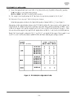
Connect the T1 or E1 signal.
T1 signal connection for
100 ohm line:
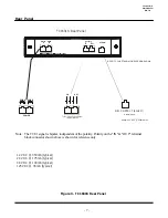
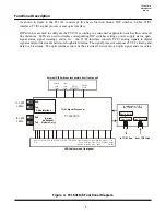
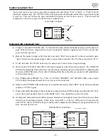
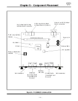
Connect the incoming T1 signal (from your equipment) to the "in"
terminal blocks on the rear panel; they are not polarity sensitive. A valid T1 signal will cause the "LOCRD"
LED turn "On." Connect the outgoing T1 signal (received from the optical cable) to the "out" terminal blocks.
E1 signal connection
(The E1 interface can be used for either 75 or 120 ohm line - see Appendix A):
75 ohm line
:
Connect the incoming signal (from your equipment) to the "in" BNC adapter. Connect the
outgoing signal (received from optical cable) to the "out" BNC adapter.
120 ohm line:
If twisted-pairs are used, connect the wires in the same way as the T1's wire. If dual coaxial
is used, connect the cores to the "in" terminal blocks for the incoming signal and to the "out" terminal blocks
for the outgoing signal (each cable has two cores & a shield).
4.
Verify optical connections:
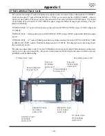
Make sure the local TC1631's optic "TxA" is connected to the remote TC1631's optic "RxA" (and vice-
versa).
For dual optical models only, make sure the local TC1631's optic "TxB" is connected to the remote TC1631's
optic "RxB" (and vice-versa).
5.
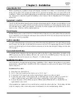
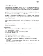
Connect power to both units.
System Start Up
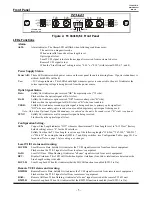
When power is initially connected, the following conditions should be observed:
1.
The "POWER A" and/or "B" LED is lit.
2.
The "LOCRD" LED is On, indicating a valid T1 or E1 signal input.
3.
The "ALARM" LED should be Off.
Start the T1/E1 signal transmission:
4.
The "POWER A" and/or "B" LED should be solidly lit.
5.
The "SYNC" LED should be lit, indicating a valid optic signal is received.
6.
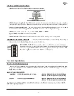
The "LEN" copper Line Length LED will generally be "Off" since "0 to 133 feet" is the factory
default setting.
Lit when any of the following copper line lengths "134-266," "267-399," "400-533," or "534-655" feet
is selected. (
See Important Note on page 2
.)
Note: If the modem is not functioning properly at this point, please refer to Chapter 3 - Troubleshooting.


