Taylor RD25 Operator'S Manual Download Page 20

16

Models RD30/RC25

Operating Procedures

150706

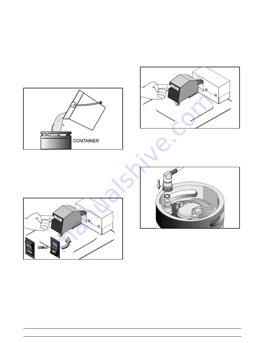
For units equipped with a post mix valve, the

following procedure is to be used in place of Step

1 - 2 of the Sanitizing Procedure.

Prepare a pail of approved 100 PPM sanitizing solution

(examples: 2- 1/2 gal. [9.5 liters] of Kay- 5

R

or 2 gal.

[7.6 liters] of Stera- Sheen

R

). USE WARM WATER

AND

FOLLOW

THE

MANUFACTURER’S

SPECIFICATIONS. Pour the solution into a clean,

empty mix delivery system container.

Figure 24

Place the control switch in the “WASH” position. Place

the “FILL” switch in the “ON” position. To prime the fill

valve, press and hold the area marked “PUSH” on the

front of the post mix valve (prime button). After 10

seconds, release the valve and the sanitizing solution

will continue to flow until the mix float is satisfied or until

the fill switch is turned to the “OFF” position.

Figure 25

Note:

If the sanitizing solution does not continue to

flow after releasing the prime button, press and hold

the prime button for an additional ten (10) seconds.

Repeat this procedure as required to prime the post

mix valve.

Figure 26

Drain the sanitizing solution from the freezing cylinder

and repeat this procedure until all the sanitizing

solution is dispensed from the mix delivery container.

Disconnect the mix delivery container.

Figure 27

IMPORTANT!

The unit must NOT be placed in AUTO

until all sanitizing solution has been removed from the

freezing cylinder and proper priming procedures have

been completed. Failure to follow this instruction may

result in damage to the freezing cylinder.

Summary of Contents for RD25

Page 1: ...OPERATOR S MANUAL Model RD30 RC25 Remote Slush Freezer Original Operating Instructions 051060 M 11 99 Original Publication Updated 7 6 15...

Page 2: ...l Refrigeration Inc 051060 M Any unauthorized reproduction disclosure or distribution of copies by any person of any portion of this work may be a violation of Copyright Law of the United States of Am...

Page 3: ...2 To the Operator 5 Section 3 Safety 6 Section 4 Operator Parts Identification 8 Section 5 Important To the Operator 10 Control Switch 10 Fill Switch 10 Mix Out Light 10 Viscosity Control 10 Section 6...

Page 4: ...Only instructions originating from the factory or its authorized translation representative s are considered to be the original set of instructions E 1999 Carrier Commercial Refrigeration Inc Origina...

Page 5: ...o performing any repairs Failure to follow this instruction may result in personal injury or death from electrical shock or hazardous moving parts as well as poor performance or damage to the equipmen...

Page 6: ...o disconnect the appliance from the power source must have an all pole disconnecting device with a contact gap of at least 3 mm installed in the external installation S Appliances that are permanently...

Page 7: ...sorbed by the oil Refrigeration Charging and Line Construction The dispensing unit is shipped with a refrigerant holding charge that is sufficient enough to prevent moisture contamination 8 oz 227 g R...

Page 8: ...ystem Priming is required until the B I B switch and the float switch are both satisfied Priming is complete when product will flow without pressing the PUSH button Step 4 To adjust either the syrup o...

Page 9: ...lation in effect after August 13 2005 Therefore it must be collected separately after its use is completed and cannot be disposed as unsorted municipal waste The user is responsible for returning the...

Page 10: ...inse the freezer Failure to follow these instructions may result in serious electrical shock S DO NOT operate the freezer unless it is properly grounded S DO NOT operate the freezer with larger fuses...

Page 11: ...far as safety and hygiene are concerned This freezer must be placed on a level surface Failure to comply may result in personal injury Cleaning and sanitizing schedules are governed by your state or l...

Page 12: ...Clip 049419 4 Panel A Rear X48983 5 Panel Side Right 048977 6 Leg A 4 3 8 16 Stud w Cap X43408 7 Panel Side Left 048975 8 Stud Freezer 034035 ITEM DESCRIPTION PART NO 9 Washer Freezer Stud 049032 10 P...

Page 13: ...Zero Waste 047353 1h O Ring 7 8 OD x 103 W 014402 1i Door A Partial X50172 2 O Ring 5 5 OD x 5 234 ID x 13 049077 3 Bearing Front 013116 ITEM DESCRIPTION PART NO 4 Arm Torque 014500 5 O Ring 291 ID x...

Page 14: ...nables the fill module to replenish and maintain product levels in the freezing cylinder and in the hopper The OFF position terminates the fill function The refrigeration system is disabled when the f...

Page 15: ...e Taylor Lube HP Every three months discard rubber parts and install new rubber parts Step 1 Lubricate the o ring groove Slide the o ring into the first groove on the drive shaft Lubricate the groove...

Page 16: ...r the rear holding pin knife edge to the outside Holding the blade on the beater turn it over and install the front blade the same way Figure 6 Step 5 Holding the blades in position insert the beater...

Page 17: ...the door assembly including the inside of the draw valve bore Replace any damaged parts Step 9 Slide the draw valve o ring into the groove on the draw valve and lubricate the o ring Figure 11 Step 10...

Page 18: ...side of the door and lubricate the o ring Install the door bearing onto the hub on the back side of the door with the flanged end of the bearing facing the door Figure 17 Note Do not lubricate the doo...

Page 19: ...URER S SPECIFICATIONS Pour the solution into a clean empty mix delivery container Connect the container to the mix delivery line Figure 22 Step 2 Place the control switch in the WASH position Press th...

Page 20: ...release the valve and the sanitizing solution will continue to flow until the mix float is satisfied or until the fill switch is turned to the OFF position Figure 25 Note If the sanitizing solution d...

Page 21: ...ch Figure 29 Step 5 Place the control switch in the WASH position This will cause the sanitizing solution in the freezing cylinder to be agitated Allow the solution to agitate for five minutes Figure...

Page 22: ...p 2 Place the control switch in the AUTO position When the unit cycles off the product will be at serving viscosity The viscosity thickness of the slush can be adjusted by turning the viscosity adjust...

Page 23: ...HE MANUFACTURER S SPECIFICATIONS Step 2 Pour the cleaning solution into the hopper and allow it to flow into the freezing cylinder Step 3 Once the mix float switch is submerged in the cleaning solutio...

Page 24: ...torque rotor S scraper blades from the scraper blade clips Note To remove o rings use a single service towel to grasp the o ring Apply pressure in an upward direction until the o ring pops out of its...

Page 25: ...f syrup j 8 On a regular basis take a brix reading to assure a consistent quality product post mix valve systems only Regular Maintenance Checks j 1 Replace scraper blades that are nicked or damaged j...

Page 26: ...refully b Missing incorrectly installed or worn scraper blades b Replace or install the blades correctly 12 c The viscosity adjustment screw needs to be adjusted c Adjust the screw accordingly 3 10 d...

Page 27: ...is bent e Call service technician to repair or replace the beater and to correct the cause of insufficient mix in the freezing cylinder 5 Unable to remove the drive shaft a There is lubrication on the...

Page 28: ...e the torque rotor b The torque arm is bent b Replace the torque arm c The condensers are dirty c Clean the condensers monthly 21 d The fill system switch is not in the ON position d Turn the fill swi...

Page 29: ...RT DESCRIPTION EVERY 3 MONTHS EVERY 6 MONTHS ANNUALLY Scraper Blade Inspect Replace if Necessary Minimum Drive Shaft Seal X Freezer Door O Ring X Door Port O Ring X Front Bearing X Door Spout O Ring X...

Page 30: ...eration compressor except service valve Five 5 years Beater motors Two 2 years Beater drive gear Two 2 years Printed circuit boards and Softech controls beginning with serial number H8024200 Two 2 yea...

Page 31: ...s resulting from the use of any refrigerant other than that specified on the Product s data label will void this limited warranty 13 Any cost to replace refill or dispose of refrigerant including the...

Page 32: ...s Twelve 12 months Class 512 Parts Twelve 12 months Class 000 Parts No warranty Taylor Part 072454 Motor 24VDC C832 C842 Four 4 years LIMITED WARRANTY CONDITIONS 1 If the date of original installation...

Page 33: ...ice work promptly upon arrival 9 Failure damage or repairs due to faulty installation misapplication abuse no or improper servicing unauthorized alteration or improper operation or use as indicated in...

Page 34: ...LOST SALES LOST PROFITS PRODUCT LOSS PROPERTY DAMAGES OR SERVICE EXPENSES ARE EXPRESSLY EXCLUDED THE EXPRESS WARRANTIES MADE IN THIS LIMITED WARRANTY MAY NOT BE ALTERED ENLARGED OR CHANGED BY ANY DIS...

Reviews: