background image

Section 3

3-1 

Models 8752, 8756, and 8757 

Safety 

 3

Safety

We at Taylor Company are concerned about the safety of 
the operator when he or she comes in contact with the 
freezer and its parts. Taylor has taken extreme efforts to 
design and manufacture built-in safety features to protect 
both you and the service technician. As an example, 
warning labels have been attached to the machine to 
further point out safety precautions to the operator.

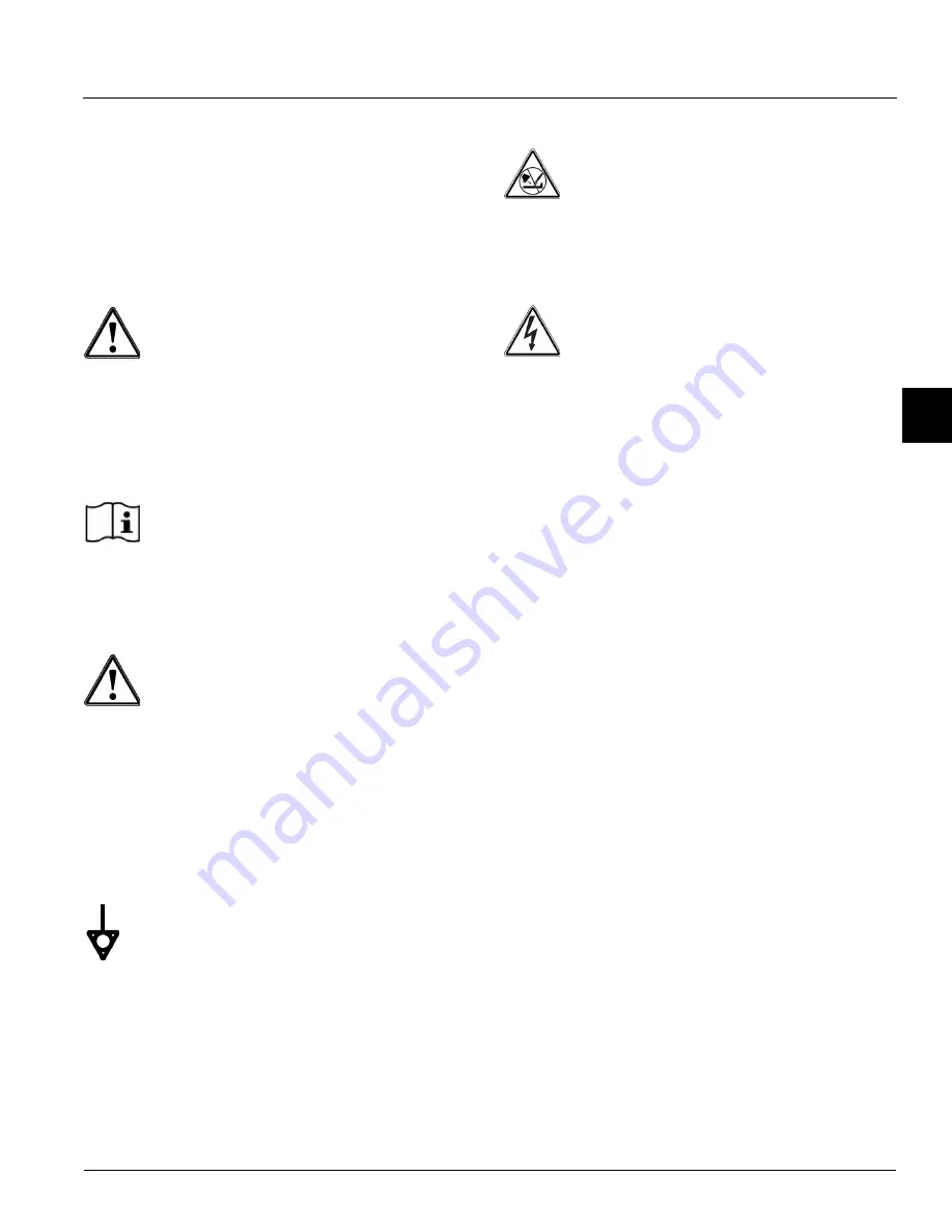
DANGER! 

Failure to adhere to the following 

safety precautions may result in severe personal injury or 
death. Failure to comply with these warnings may also 
damage the machine and/or its components. Such 
damage may require component replacement and 
service repair expenses

.

NOTICE! DO NOT

 operate this machine 

without reading this entire manual first. Failure to follow 
all of these operating instructions may result in damage 
to the machine, poor performance, health hazards, or 
personal injury.

IMPORTANT! 

This machine is to be used only 

by trained personnel. It is not intended for use, cleaning, 
or maintenance by children or people with reduced 
physical, sensory, or mental capabilities or lack of 
experience and knowledge, unless given supervision or 
instruction concerning the use of the machine by a 
person responsible for their safety. Children should be 
supervised to ensure that they do not play with the 
machine.

IMPORTANT! 

An equipotential grounding lug is 

provided with this machine. Some countries require the 
grounding lug to be properly attached to the rear of the 
frame by the authorized installer. The installation location 
is marked by the equipotential bonding symbol (5021 of 
IEC 60417-1) on both the removable panel and the 
machine's frame.

WARNING! 

This machine must 

NOT

 be 

installed in an area where a water jet or hose can be 
used. 

NEVER 

use a water jet or hose to rinse or clean 

the machine. Failure to follow this instruction may result 
in electrocution.

WARNING!

 Avoid injury.

DO NOT

 operate the machine unless it is 

properly grounded.

DO NOT

 operate the machine with fuses larger 

than specified on the machine's data label.

All repairs should be performed by an 

authorized Taylor service technician.

The main power supplies to the machine must 

be disconnected prior to performing installation, 
repairs, or maintenance.

For Cord-Connected Machines: 

Only Taylor 

service technicians or licensed electricians may 
install a plug or replacement cord on the 
machine.

Machines that are permanently connected to 

fixed wiring and for which leakage currents may 
exceed 10 mA, particularly when disconnected 
or not used for long periods, or during initial 
installation, shall have protective devices to 
protect against the leakage of current, such as a 
GFI, installed by the authorized personnel to 
local codes.

Stationary machines that are not equipped with 

a power cord and a plug or another device to 
disconnect the appliance from the power source 
must have an all-pole disconnecting device with 
a contact gap of at least 0.125 in. (3 mm) in the 
external installation.

Supply cords used with this machine shall be 

oil-resistant, sheathed flexible cable not lighter 
than ordinary polychloroprene or other 
equivalent synthetic elastomer-sheathed cord 
(code designation 60245 IEC 57) installed with 
the proper cord anchorage to relieve conductors 
from strain, including twisting, at the terminals 
and protect the insulation of the conductors from 
abrasion.

Summary of Contents for Horizon 8752

Page 1: ...OPERATOR S MANUAL Model 8752 8756 and 8757 Soft Serve Freezers Original Operating Instructions 028752 M 08 99 Original Publication Updated 8 11 2020...

Page 2: ..._______ Phase__________________________________ Maximum Fuse Size ___________________________________________________Amps Minimum Wire Ampacity ________________________________________________Amps Not...

Page 3: ...bly 4 3 Model 8756 4 4 Model 8757 4 6 8756 and 8757 Beater Door Assembly 4 8 Accessories 4 9 Section 5 User Interface Symbol Definitions 5 2 Power Switch 5 2 RESET Button 5 2 Softech Control Operation...

Page 4: ...aning and Sanitizing 7 1 Troubleshooting Bacterial Count 7 1 Regular Maintenance Checks 7 1 Air Mix Pump 7 2 Winter Storage 7 2 Section 8 Troubleshooting Guide Section 9 Parts Replacement Schedule Sec...

Page 5: ...pairs Failure to follow this instruction may result in personal injury or death from electrical shock or hazardous moving parts as well as poor performance or damage to the machine WARNING This machin...

Page 6: ...to an open trap drain IMPORTANT A backflow prevention device is required on the incoming water connection side Please see the applicable national state and local codes for determining the proper conf...

Page 7: ...nt or a similarly qualified person to avoid a hazard Secure supply cord ground lead to machine in a location where if the cord is pulled the main power leads become taut before the ground lead can bre...

Page 8: ...g and reclaiming systems For information regarding applicable local laws please contact your local authorized Taylor distributor IMPORTANT Refrigerants and their associated lubricants may be extremely...

Page 9: ...lor warranty is valid only if the parts are authorized Taylor parts purchased from the local authorized Taylor distributor and only if all required service work is provided by a Taylor service technic...

Page 10: ...she employs It should also be noted that Taylor does not warrant the refrigerant used in its machine For example if the refrigerant is lost during the course of ordinary service to this machine Taylo...

Page 11: ...potential bonding symbol 5021 of IEC 60417 1 on both the removable panel and the machine s frame WARNING This machine must NOT be installed in an area where a water jet or hose can be used NEVER use a...

Page 12: ...ne must be installed on a level surface to avoid the hazard of tipping Extreme care should be taken in moving this equipment for any reason Two or more persons are required to safely move this machine...

Page 13: ...dels 8752 8756 and 8757 Safety 3 Noise Level Airborne noise emission does not exceed 78 dB A when measured at a distance of 39 in 1 0 m from the surface of the machine and at a height of 62 in 1 6 m f...

Page 14: ...3 4 SAFETY Models 8752 8756 and 8757 Safety 3 Notes...

Page 15: ...ection 4 4 1 Models 8752 8756 and 8757 Operator Parts Identification 4 Model 8752 Figure 4 1 8 2 3 1 10 13 26 27 22 23 20 28 5 4 6 7 9 12 11 21 25 15 17 16 24 19 18 14 21 Operator Parts Identification...

Page 16: ...028600 10 Pan Drip 11 5 8 Long 027503 11 Caster 3 SWV 3 4 10 Stem 021279 12 Gasket Mix Door 020134 13 Probe A Mix w Handle X35981 14 Boot Mix Cover 037200 Item Description Part No 15 Tank Mix 15 Gall...

Page 17: ...Front 050347 5b Bearing Front Shoe 050348 5c Shoe Front Helix Rear 050346 6 Gasket Door HT 4 Double 048926 7 Door A 1 Spout X51531 10 7a Baffle A Log 4 in X50882 8 Handle A Draw Adj 8a 8d X55096 8a H...

Page 18: ...4 4 OPERATOR PARTS IDENTIFICATION Models 8752 8756 and 8757 Operator Parts Identification 4 Model 8756 Figure 4 3 15 22 12 16 19 2 18 6 11 14 20 17 21 22 7 23 9 10 8 4 26 5 3 29 27 13 28 24 1 25 15a...

Page 19: ...r 3 SWV 3 4 10 Stem 021279 12 Gasket Cab Mix Door 024629 13 Probe A Mix w Handle X35981 14 Boot Cover Mix 037200 15 Tank A Mix w Decals X38755 SER Item Description Part No 15a Tank Mix 9 Gallon 034928...

Page 20: ...4 6 OPERATOR PARTS IDENTIFICATION Models 8752 8756 and 8757 Operator Parts Identification 4 Model 8757 Figure 4 4 22 12 15 17 16 18 14 20 21 19 29 27 11 13 28 6 7 5 23 9 10 8 4 22 3 26 24 25 2 1 15a...

Page 21: ...Swivel 3 4 10 ST 021279 12 Gasket Cabinet Mix Door 024629 13 Probe A Mix w Handle X35981 14 Boot Mix Cover 037200 15 Tank Mix X38755 SER 15a Tank Only 034928 Item Description Part No 16 Cover Mix Tan...

Page 22: ...050348 5c Shoe Front Helix Rear 050346 6 Gasket Door HT 4 Double 048926 7 Door A 3 Spout X51532 12 7a Baffle A Long 4 in w Rad X50882 8 Handle A Draw 8a 8c X81010 SP 8a Handle A Adj Theaded X80889 SP...

Page 23: ...5 8 2 10 7 9 Item Description Part No 1 Brush Mix Pump Body 3 x 7 023316 2 Brush Pressure Switch 1 8 027647 3 Brush Feed Tube 9 16 x 44 021101 4 Brush Double Ended 013072 5 Brush Rear Bearing 1 x 2 x...

Page 24: ...4 10 OPERATOR PARTS IDENTIFICATION Models 8752 8756 and 8757 Operator Parts Identification 4 Notes...

Page 25: ...Section 5 5 1 Models 8752 8756 and 8757 User Interface 5 User Interface Figure 5 1 Model 8752 Model 8756 Model 8757 9 2 4 3 1 2 1 9 8 7 6 5 4 3 3 4 2 1 8 9 7 5 6 8 7 10 6 5...

Page 26: ...th sides to resume normal operation If the machine shuts down again contact a service technician Indicator Lights MIX LOW When the MIX LOW light begins to flash the mix tank has a low supply of mix an...

Page 27: ...en the STANDBY button is pressed the light comes on indicating the cylinder temperature retention system CTR has been activated In the Standby mode the Wash Pump and Auto functions are automatically c...

Page 28: ...5 4 USER INTERFACE Models 8752 8756 and 8757 User Interface 5 Notes...

Page 29: ...the heater switch in the ON position Note This heating process will take approximately 2 5 hours to reach temperature The water level in the topping wells must be checked at least once daily 3 Prepare...

Page 30: ...of wear or damage If a scraper blade is nicked or worn replace both blades Figure 6 4 4 If the blades and clips are in good condition place the rear scraper blade over the rear holding pin on the beat...

Page 31: ...luding the inside of the draw valve bore Replace any damaged parts 11 Place the large rubber gasket s in the groove s on the back side of the freezer door Slide the white plastic front bearing s over...

Page 32: ...inside of the freezer door spout s top and bottom and insert the draw valve s from the bottom until the slot in the draw valve s comes into view Figure 6 13 17 Install the adjustable draw handle s Sli...

Page 33: ...is to meter a specific amount of air and mix and transfer this combination to the freezing cylinder Refer to the illustration on page 6 9 for identification of parts during assembly 1 Inspect the rubb...

Page 34: ...alve body into the pump cylinder and push upward Align the steel button at the base of the liquid valve body with the cut out groove at the bottom of the pump cylinder Note The drive hole in the pisto...

Page 35: ...allow the weighted end to hang free Figure 6 28 12 Push both nuts back from the flare end and lightly lubricate the underside of the plastic flare This will allow the nut to turn freely without twisti...

Page 36: ...Severe and costly damage may occur if it is not properly aligned 17 Lubricate both sides of the pressure switch diaphragm Figure 6 33 18 Place the diaphragm on the front face of the pressure switch ho...

Page 37: ...ag 020051 3f Body A Valve X36202 3g O ring 13 6 OD x 139W 50 Per Bag 21278 3h Elbow Inlet 90 Deg 022502 4 3i Spring Tapered 1 7 8L 022456 3j Poppet Rubber Black 022473 3k Ring Check 1 1 4 in OD x 3 8...

Page 38: ...tube with the long brush and sanitizing solution Figure 6 36 4 Connect the free end of the flare line to the threaded fitting on the mix inlet tube Figure 6 37 5 Install the pressure line Attach the q...

Page 39: ...on is flowing from the prime plug hole in the bottom of the freezer door press the PUMP button stopping pump operation Push down the prime plug and allow beater agitation for 5 minutes Figure 6 44 12...

Page 40: ...x tank Connect the mix probe in the socket receptacle Figure 6 46 3 Place the free end of the suction line down in the mix tank Figure 6 47 Important Use only fresh mix when priming the machine 4 Inst...

Page 41: ...To disassemble Models 8752 8756 and 8757 the following items will be needed Two cleaning and sanitizing pails Sanitized stainless steel rerun can with lid Cleaning brushes provided with machine Clean...

Page 42: ...xamples 2 1 2 gal 9 5 L of Kay 5 or 2 gal 7 6 L of Stera Sheen Use warm water and follow the manufacturer s specifications Place the pail of cleaning solution inside the mix cabinet and insert the suc...

Page 43: ...the O ring Apply pressure upwards until the O ring pops out of its groove With the other hand push the top of the O ring forward It will roll out of the groove and can be easily removed If there is mo...

Page 44: ...screwdriver loosen and remove the screws from the lower right panel Locate the adjustment screws one for each water bath 5 Using a flatblade screwdriver turn the adjustment screw clockwise to increase...

Page 45: ...ard then mix the rerun with fresh mix in a ratio of 50 50 during the day s operation On a designated day of the week run the mix as low as feasible and discard after closing This will break the rerun...

Page 46: ...ely attached to the pressure switch Clean sanitize and lubricate the pressure switch diaphragm daily Make sure the air mix pump is properly aligned with the face plate of the motor reducer or severe a...

Page 47: ...Reset the freezer 5 1 d The beater assembly is rotating counterclockwise d Contact service technician to correct rotation to clockwise e Insufficient mix in the freezing cylinder e Go to problem 2 f...

Page 48: ...n the pump drive motor Return the power switch to the ON position Press the AUTO button For Models 8756 and 8757 press the AUTO button for the opposite freezing cylinder also g Defective air mix pump...

Page 49: ...door must be kept closed 6 13 c The mix cabinet refrigeration system needs adjustment c Contact a service technician d The mix cabinet door gasket is not sealing d Repair or replace gasket e Dirty mix...

Page 50: ...eturn the power switch to the ON position On Models 8756 and 8757 press the AUTO button for the opposite freezing cylinder also b Defective air mix pump pressure switch b Contact a service technician...

Page 51: ...ck Band X 3 Mix Inlet Fitting O ring X 1 Pressure Switch Diaphragm X 1 Design Cap X 1 White Bristle Brush 9 16 in x 44 in 14 mm x 1 12 m Inspect and replace if necessary Minimum 1 White Bristle Brush...

Page 52: ...9 2 PARTS REPLACEMENT SCHEDULE Models 8752 8756 and 8757 Parts Replacement Schedule 9 Notes...

Page 53: ...al number Proof of purchase may be required at time of service 2 This limited warranty is valid only if the Product is installed and all required service work on the Product is performed by an authori...

Page 54: ...resulting from the use of any refrigerant other than that specified on the Product s data label will void this limited warranty 13 Any cost to replace refill or dispose of refrigerant including the co...

Page 55: ...se may be required at time of service 2 This limited warranty is valid only if the Part is installed and all required service work in connection with the Part is performed by an authorized Taylor dist...

Page 56: ...arranty service work promptly upon arrival 9 Failure damage or repairs due to faulty installation misapplication abuse no or improper servicing unauthorized alteration or improper operation or use as...

Page 57: ...OR INCIDENTAL DAMAGES INCLUDING CLAIMS FOR LOST SALES LOST PROFITS PRODUCT LOSS PROPERTY DAMAGES OR SERVICE EXPENSES ARE EXPRESSLY EXCLUDED THE EXPRESS WARRANTIES MADE IN THIS LIMITED WARRANTY MAY NOT...

Page 58: ...11 4 LIMITED WARRANTY ON PARTS 8752 8756 and 8757 Limited Warranty on Parts 11 Notes...

Reviews: