OPERATING PROCEDURES
6-7
Models C709 & C717
Operating Procedures
6
Note:
Make sure the hole in the air orifice is clean
and is not clogged. If the hole in the air orifice should
become clogged, use soap and hot water to clear the
hole.
Do not
enlarge the hole in the air orifice.
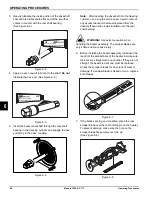
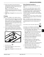
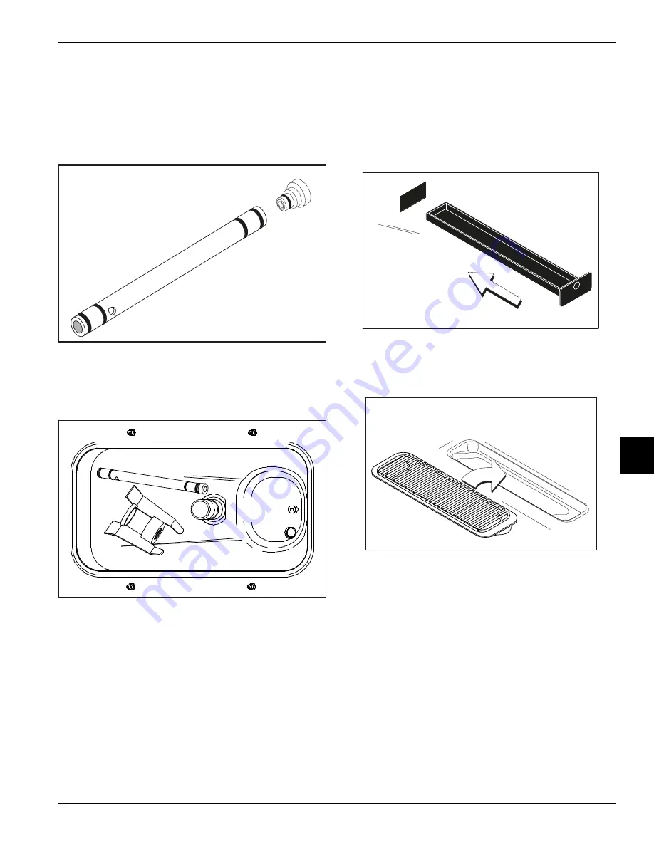
3.
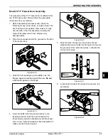
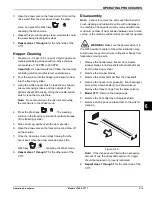
Install the air orifice into the hole in the top of the feed
tube (end without the mix delivery hole on the side).
Figure 6-28
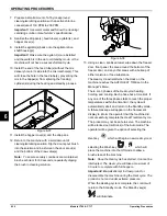
4.
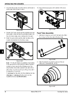
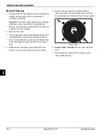
Lay the feed tube (with the air orifice installed) and
the agitator in the bottom of the mix hopper for
sanitizing.
Figure 6-29
5.
Repeat steps 1 through 4
for the other side of the
C717.
Install Drip Pans and Splash Shield
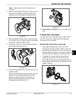
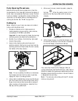
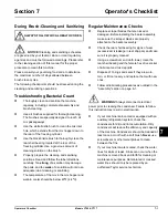
1.
Model C709:
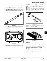
Slide the drip pan into the hole in the
left panel.
Model C717:
Slide the long drip pan into the hole in
the front panel. Slide the other two drip pans into the
holes in the side panels. (See Figure 6-30.)
Figure 6-30
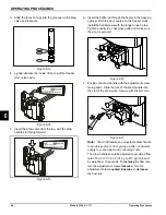
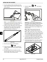
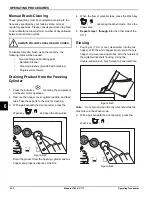
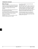
2. Install the front drip tray and splash shield under the
door spout(s). (See Figure 6-31.)
Figure 6-31
Sanitizing
1. Prepare a 2-1/2 gal. (9.5 L) pail of a Taylor-approved
cleaning/sanitizing solution with an active chlorine
concentrate of 100 PPM–200 PPM (examples: 2 gal.
[7.6 L] of Stera-Sheen
®
or 2-1/2 gal. [9.5 L] of
Kay-5
®
).
Important!
Use warm water and follow the
cleaning/sanitizing solution manufacturer's
specifications.
12078
12318
10176
10231
Summary of Contents for C709
Page 8: ...1 4 TO THE INSTALLER Models C709 C717 To the Installer 1 Notes...
Page 22: ...4 10 OPERATOR PARTS IDENTIFICATION Models C709 C717 Operator Parts Identification 4 Notes...
Page 58: ...8 4 TROUBLESHOOTING GUIDE Models C709 C717 Troubleshooting Guide 8 Notes...
Page 60: ...9 2 PARTS REPLACEMENT SCHEDULE Models C709 C717 Parts Replacement Schedule 9 Notes...
Page 64: ...10 4 LIMITED WARRANTY ON EQUIPMENT Models C709 C717 Limited Warranty on Equipment 10 Notes...
Page 68: ...11 4 LIMITED WARRANTY ON PARTS Models C709 C717 Limited Warranty on Parts 11 Notes...

