6-4
OPERATING PROCEDURES
Model C706
Operating Procedures
6
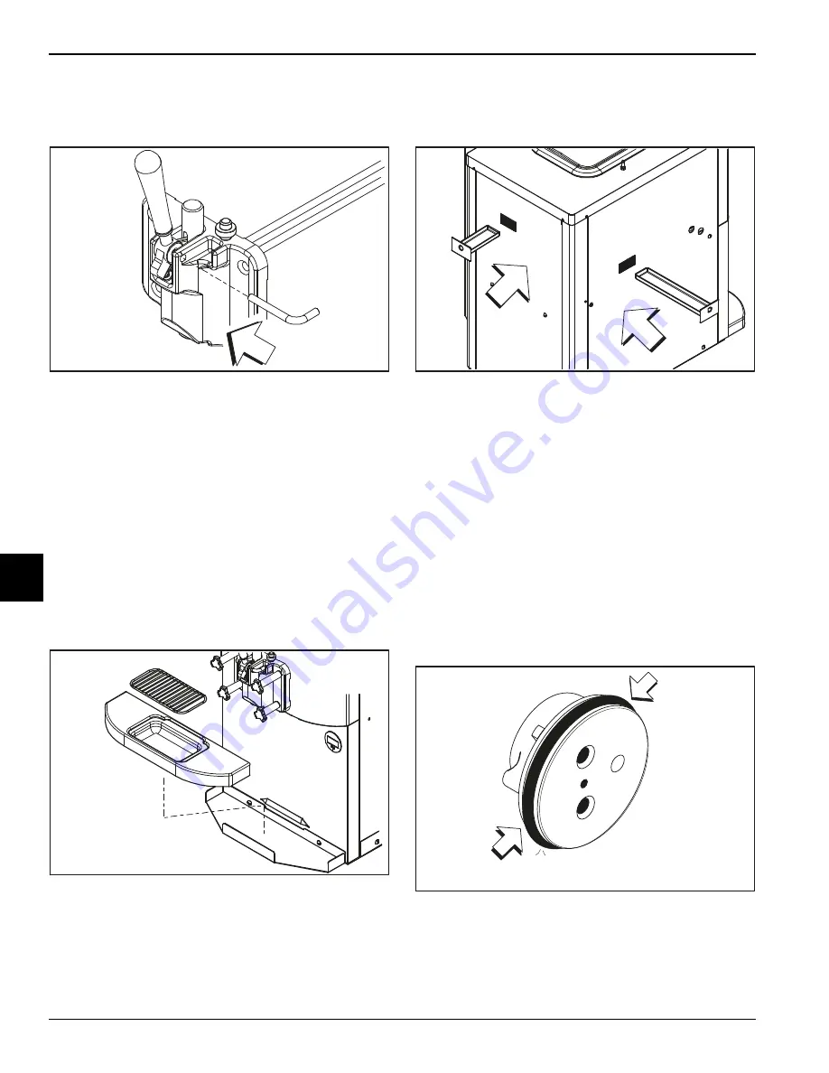
15. Install the adjustable draw handle. Slide the fork over
the bar in the slot of the draw valve. Secure it with the
pivot pin.
Figure 6-11
Note:
This machine features an adjustable draw
handle to provide the best portion control. The draw
handle can be adjusted for different flow rates. See
page 5-3 for more information on adjusting this
handle.
16. Insert the baffle rod through the opening in the beater
and seat the door flush with the freezing cylinder.
With the door seated on the freezer studs, install the
handscrews. Tighten them equally in a crisscross
pattern to ensure the door is snug.
17. Install the front drip tray and the splash shield under
the door spout.
Figure 6-12
18. Slide the rear drip pan into the hole in the side panel.
Slide the pump drip pan into the hole in the back
panel.
Figure 6-13
Mix Hopper Assembly
1. Inspect the rubber and plastic pump parts. The
O-rings, check rings, and gaskets must be in 100%
good condition for the pump and machine to operate
properly. They cannot work properly if nicks, cuts, or
holes are present. Inspect the plastic pump parts for
cracks, wear, and delamination of plastic. Replace
any worn or damaged parts immediately and discard
the old parts.
2. Assemble the mix inlet assembly. Slide the O-ring
into the groove of the valve body cap.
Do not
lubricate the O-ring.
Figure 6-14
10503
10504
10357
15109
Summary of Contents for C706
Page 8: ...1 4 TO THE INSTALLER Model C706 To the Installer 1 Notes ...
Page 14: ...3 4 SAFETY Model C706 Safety 3 Notes ...
Page 36: ...6 14 OPERATING PROCEDURES Model C706 Operating Procedures 6 Notes ...
Page 42: ...8 4 TROUBLESHOOTING GUIDE Model C706 Troubleshooting Guide 8 Notes ...
Page 44: ...9 2 PARTS REPLACEMENT SCHEDULE Model C706 Parts Replacement Schedule 9 Notes ...
Page 48: ...10 4 LIMITED WARRANTY ON EQUIPMENT Model C706 Limited Warranty on Equipment 10 Notes ...
Page 52: ...11 4 LIMITED WARRANTY ON PARTS Model C706 Limited Warranty on Parts 11 Notes ...


