background image

10

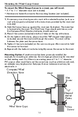
To mount the Wind Gauge Sensor to a mast, you will need:

 A 1” to 1 ¼” diameter mast (

not included

). 

 Hardware to fasten the mast to the mounting location (

not included

). 

1.

 If necessary, mount and ground a mast at the selected location (s

uch as a 

roof or fence post

) as directed in the instructions provided by the mast (

not 

included

).

2.

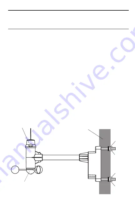
 Hold the Sensor base up against the mast (

see illustration

). The metal bar 

is horizontal to the mast. The Wind Vane Cups should point down, and 
the Compass/Wind Direction Indicator should point up. 

3.

 Place 2 hex screws (

included

) into the 2 holes on the top of the base.

4.

 On the bottom of the base, place one of the 

“U”

 shaped metal plates 

(

included

) around the mast and through the screws. The mast will be 

between the plate and the sensor base.

5.

 Tighten 2 hex nuts (

included

) on the screws using an Allen wrench to hold 

the sensor to the mast.

6.

 Repeat with the bottom two holes to tightly secure the sensor to the mast.

Mounting Option:


If another mast has been previously installed (for 

example, for mounting an antenna), the wind gauge sensor may be mounted 
on that existing mast. Or, if there is an existing piece of 1 to 1 ¼” diameter 
PVC pipe or other mast that is not the correct size (such as a kitchen sink vent), 
an extender may be placed on that pipe, then an extension mast may be 
attached to it.

Mounting the Wind Gauge Sensor

Wind Vane Cups

Mast

“U” 

Shaped

Metal

Plates

Compass/Wind 

Direction Vane

Hex
Screw

Hex
Screw

Summary of Contents for 2752

Page 1: ...Instruction Manual Digital Wireless Weather Station with Wind Speed Sensor Leading the Way in Accuracy 2752...

Page 2: ...ure humidity data to the receiver unit 3 Mounting hardware for the Wind Gauge Sensor 2 U shaped metal plates 4 sets of Hex screws nuts 4 Instruction manual Additional items needed for installation not...

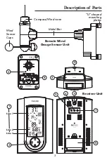
Page 3: ...8 8 3 Description of Parts 9 10 Compass Wind vane Wind Sensor Cups Metal Bar U shaped mounting plates Receiver Unit Remote Wind Gauge Sensor Unit Line 3 Line 1 Line 2 1 2 4 5 6 7 3...

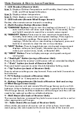
Page 4: ...D Button Press to display average wind speeds and gust wind speed 4 Backlight Button on top of Receiver Unit Press to illuminate the receiver s LCD screen with an extended backlight 5 Clock button on...

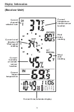
Page 5: ...channel selected icon Current indoor temperature Heat index reading Current humidity at remote sensor location Current temperature remote sensor location Wind chill reading Current time calendar displ...

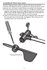
Page 6: ...e back side of the compass there is a hollow area that will fit onto the wind sensor base unit Align the hole in the center of the hollow area with the metal prong on the base unit Push gently on the...

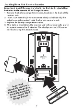
Page 7: ...t 2 AA batteries lithium recommended as indicated by the polarity symbols marked inside the battery compartment 3 Replace the battery compartment cover 4 After battery installation the receiver unit w...

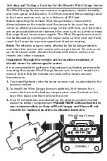
Page 8: ...where the receiver and remote units are positioned Try various set ups for the best results Shorten the distance between receiver and remote units when necessary Important Though the remote unit is we...

Page 9: ...ration steps The batteries will be reinstalled later after the Wind Gauge s direction is calibrated North see section on Calibrating the Wind Gauge Sensor Installing Batteries IMPORTANT Before mountin...

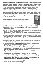
Page 10: ...place one of the U shaped metal plates included around the mast and through the screws The mast will be between the plate and the sensor base 5 Tighten 2 hex nuts included on the screws using an Alle...

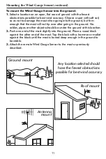
Page 11: ...pes or other objects should be under the ground at this location 2 Push one end of the mast slightly into the ground Place a wood block against the other end of the mast Tap the block with a hammer or...

Page 12: ...he Wind Direction Indicator so it is pointing due north Hold the Pointer facing due north do not allow it to turn 3 Insert 2 AA batteries as indicated by the polarity symbols marked inside the battery...

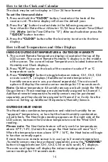
Page 13: ...ove the cover 4 Assign channel 2 or 3 to the remote sensor by setting the slide switch inside the battery compartment Channel 1 is already assigned to the Wind Gauge Sensor and should not be used by a...

Page 14: ...e in use purchased separately The auto scroll option will display the remote sensor readings for 10 seconds each Note Outdoor temperature humidity sensors are built inside the Wind Gauge Sensor These...

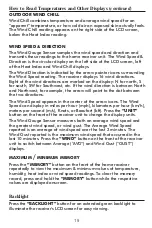
Page 15: ...int to the dot between the two directions The Wind Speed appears in the center of the arrow icons The Wind Speed can display in miles per hour mph kilometers per hour km h meters per second m s Knots...

Page 16: ...to radio communications However there is no guarantee that interference will not occur in a particular installation If this equipment does cause harmful interference to radio or television reception w...

Page 17: ...ither unit with abrasive or corrosive materials This may scratch plastic parts and corrode electronic circuits 8 Do not subject either unit to excessive force shock dust temperature or humidity This m...

Page 18: ...ate For additional product information or warranty information in Canada or elsewhere outside the USA please contact us through www taylorusa com Range of temperature measurement Receiver unit indoor...

Reviews: