background image

m

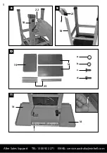
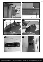
7.2 Attaching the table length and width
extensions (Fig. 10-14)

• 

Loosely attach the table width and length 

extensions (14/15) to the saw bench (1) with 

the hex screws (c), washers (a) and nuts (b). 
(Figure 12-13).

• 

Screw the supports (23) loosely to the housing 

of the bench saw and to the table width/

length extensions. (Short supports for width 
extension, long supports for length extension) 
(Fig 13-14).

• 

Adjust the table width and length according to 
the saw bench (1).

• 

Finally, tighten all screws.

• 

Turn the saw and base frame around and set it 

on the floor.

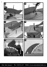
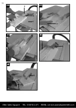
7.3 Assembling/disassembling the saw
blade guard (Fig. 2, 15-16)

• 

Set the saw blade guard (2) with screw (24) 
from above onto the splitter (4), so that the 

screw sits firmly in the oval hole (25).

• 

Do not tighten the screw (24) too much; the 
saw blade must be able to move freely.

• 

Attach the extractor hose (3) to the extractor 
adapter (16) and to the extraction port of the 
saw blade guard (2) and screw them to the 
extractor adapter with the safety clamp (16).

• 

Connect a suitable chip extraction system to 
the extractor adapter (16). 

• 

To dismantle, proceed in reverse order. 

Caution: Before starting to saw, the saw 
blade guard (2) must be lowered onto to the 
workpiece.

7.4 Replacing the table insert (Fig. 17-18)

• 

If the table insert is worn or damaged, it 
should be replaced, otherwise risk of injury is 
increased.

• 

Take off the saw blade guard (2) (see 7.3)

• 

Remove the 2 countersunk screws (26)

• 

Remove the worn table inserts (6)

• 

Assembly of the new table inserts is to be 
carried out in reverse order. 

7.5 Adjusting the splitter (Fig. 19-20)

• 

Caution: Pull out the power plug.

• 

Set the saw blade (5) to max. cutting depth.

• 

Adjust and lock the cutting depth into the 0° 
position (see Fig. 8.2).

• 

Disassemble the saw blade guard (see 7.3)

• 

Remove the table inserts (6) (see 7.4)

• 

Loosen the fixing screws (27).

7.5.1 Setting for maximum cuts

• 

Push up the splitter (4) until the gap between 
the saw table (1) and the upper edge of the 
splitter (4) is at 10cm.

• 

The distance between saw blade (5) and 
splitter (4) should be a maximum of 5mm. (Fig. 
20)

• 

Re-tighten the screws (27) and assemble the 
table inserts (6) (see 7.4).

19

After Sales Support      TEL: 1300 922 271     EMAIL: [email protected]

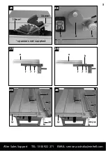
7.6 Assembly/Changing the saw blade
(Fig. 21)

• 

Caution: Pull out the power plug first.

• 

Detach the saw blade guard (2) (see Fig. 7.3).

• 

Remove the table inserts by loosening the 2 
countersunk screws (see 7.4)

• 

Loosen the nut (

Caution!

 Turn the nut in the 

direction in which the saw blade rotates) by 
using a wrench (24mm) on the nut and another 
wrench (10mm) on the motor shaft to apply 
counter-pressure.

• 

Remove the outer flange and withdraw the old 
saw blade diagonally from the inner flange.

• 

Clean the blade flange thoroughly before 
fitting the new blade.

• 

Mount and fasten the new saw blade in reverse 
order.

• 

Caution: Note the running direction. The 
cutting angle of the teeth must point in 
running direction, i.e. forwards (see the arrow 
on the blade guard).

• 

Refit and set the table insert (6) and the saw 

blade guard (2) (see 8.4, 8.5)

• 

Check to make sure that all safety devices 
are properly mounted and in good working 
condition before you begin working with the 
saw again.

8. Operation

8.1 ON/OFF Switch (Fig. 22/pos. 11)

• 

The saw can be switched on by pressing the 
green button “I”. Before starting to saw, wait 
until the saw blade has reached its maximum 
rotation speed.

• 

In order to switch the saw off again, the red 
button “0” must be pressed.

8.2 Cutting depth (Fig. 22)

• 

By turning the hand crank (8), the saw blade 
(5) can be adjusted to the desired cutting 
depth. 

Anticlockwise direction:  

Larger cutting depth

Clockwise direction:  

Smaller cutting depth

8.3 Setting the angle (Fig. 22)

• 

Loosen the locking grip (9)

• 

Set the desired angle on the scale by turning 
the handle.

• 

Lock the locking grip to the desired angularity.

8.4 Parallel stop

8.4.1. Stop height (Fig. 23-26)

• 

The stop rail (e) of the parallel stop (7) has two 
different guide faces.

• 

According to the thickness of the material to 
be cut, the stop rail must be used according 
to Fig. 25 for thick material (over 25mm 
workpiece thickness), and according to Fig. 
26 for thin material (under 25mm workpiece 
thickness.

Summary of Contents for KCTS 1700

Page 1: ...N26704 1700W BENCH TYPE CIRCULAR SAW INSTRUCTION MANUAL AFTER SALES SUPPORT TEL 1300 922 271 EMAIL service australia einhell com MODEL NUMBER KCTS 1700 ...

Page 2: ...ales support services details of which can be found in this manual and on the product itself Welcome Section Congratulations on choosing to buy a TAURUS product All products brought to you by TAURUS are manufactured to the highest standards of performance and safety and as part of our philosophy of customer service and satisfaction are backed by our comprehensive 1 Year Warranty We hope you will e...

Page 3: ...3 After Sales Support TEL 1300 922 271 EMAIL service australia einhell com 1 2 3 15 1 2 3 4 5 6 7 8 9 10 11 12 13 14 15 1 4 5 16 17 11 8 9 ...

Page 4: ...4 After Sales Support TEL 1300 922 271 EMAIL service australia einhell com 4 5 7 8 22 21 20 19 18 c b a c a 18 a b 19 c a b b a c 20 ...

Page 5: ...5 After Sales Support TEL 1300 922 271 EMAIL service australia einhell com 8 9 10 11 22 18 21 18 15 23 14 a b c d 14 1 14 d ...

Page 6: ...6 After Sales Support TEL 1300 922 271 EMAIL service australia einhell com 12 13 14 15 c a 23 a c c a b 23 a c c a b ...

Page 7: ...20 7 After Sales Support TEL 1300 922 271 EMAIL service australia einhell com 15 16 18 17 19 2 24 25 4 2 3 24 2 26 6 26 6 5 4 27 max 3 5mm ...

Page 8: ...8 After Sales Support TEL 1300 922 271 EMAIL service australia einhell com 21 22 24 23 25 26 10mm spanners not supplied 11 8 9 e f 7 f e f 7 f 12 5 e 7 28 5 12 28 7 e 24mm h ...

Page 9: ...9 After Sales Support TEL 1300 922 271 EMAIL service australia einhell com 27 28 30 29 31 32 j 12 k 12 I 28 7 45 f f 7 e 5 e 7 m 29 e 13 29 30 e f 13 f n h ...

Page 10: ...10 After Sales Support TEL 1300 922 271 EMAIL service australia einhell com 33 34 36 35 37 38 5 13 o 30 p o e q 12 33 31 34 32 34 32 2 ...

Page 11: ...11 After Sales Support TEL 1300 922 271 EMAIL service australia einhell com 39 40 42 41 43 2 4 5 1 7 17 7 5 13 5 ...

Page 12: ...er tool in unexpected situations f Dress properly Do not wear loose clothing or jewellery Keep your hair clothing and gloves away from moving parts Loose clothes jewellery or long hair can be caught in moving parts g If devices are provided for the connection of dust extraction and collection facilities ensure these are connected and properly used Use of these devices can reduce dust related hazar...

Page 13: ...p them away from your workplace 5 Store the equipment safely and securely Unused equipment must be stored in a dry locked room out of the reach of children 6 Do not overburden the tool It will work better and safer when used within its quoted capacity range 7 Use the correct tool Do not use weak tools or attachments for heavy duty work Never use the electric tool for purposes other than that for w...

Page 14: ...ic tool complies with the pertinent safety regulations Repair work may only be carried out by an electrician Otherwise there is a risk of accidents for the operator 22 Attach the dust extraction system If there are apparatuses available for the attachment of the dust extraction system make sure these are connected and used 1 3 Additional safety instructions 1 3 1 Safety measures Blades that are de...

Page 15: ...er 16 must be under supervision Keep your workplace clean of wood scrap and any unnecessary objects Persons working on the machine should not be distracted Never direct the laser beam at reflecting surfaces or persons or animals Even a low output laser beam can inflict injury on the eye Caution It is vital to follow the work procedures described in these instructions Using the equipment in any oth...

Page 16: ...intains its safety standard The machine has to be set up where it can stand securely All covers and safety devices have to be properly fitted before the machine is switched on It must be possible for the blade to run freely Pay attention to the direction of rotation of the motor and saw blade After you have switched off the motor never slow down the saw blade by applying pressure to its side Only ...

Page 17: ...aw 2 x Carbide metal covered saw blades 1 x 24 teeth 1 x 48 teeth Parallel stop Cross stop Push stick 4 Proper use The bench type circular saw is designed for the slitting and cross cutting only with the cross stop of all types of timber commensurate with the machine s size The machine is not to be used for cutting any type of round wood The equipment may only be used for the tasks it is designed ...

Page 18: ... with 2 long hex screws c washers a locking ring and nuts each Figure 8 Caution Both stability bars must be attached to the rear side of the machine Now attach the rubber feet 21 to the legs 18 Figure 9 Then screw all of the screws and nuts to the base frame 18 After Sales Support TEL 1300 922 271 EMAIL service australia einhell com 5 Technical data Motor 240 V 50Hz Power rating P S6 40 1700 W Idl...

Page 19: ...tance between saw blade 5 and splitter 4 should be a maximum of 5mm Fig 20 Re tighten the screws 27 and assemble the table inserts 6 see 7 4 19 After Sales Support TEL 1300 922 271 EMAIL service australia einhell com 7 6 Assembly Changing the saw blade Fig 21 Caution Pull out the power plug first Detach the saw blade guard 2 see Fig 7 3 Remove the table inserts by loosening the 2 countersunk screw...

Page 20: ...ade 5 Fig 30 Re tighten the screws m 20 After Sales Support TEL 1300 922 271 EMAIL service australia einhell com 8 6 Cross stop Fig 31 32 Insert the cross stop 13 into the groove 29 of the saw table Loosen knurled screw 30 Turn the cross stop 13 until the arrow points to the angle required Re tighten the knurled screws 30 When cutting larger workpieces the cross stop 13 can be lengthened with the ...

Page 21: ...epth fine cutting finish 21 After Sales Support TEL 1300 922 271 EMAIL service australia einhell com 9 1 Making long cuts Fig 39 Longitudinal cutting also known as slitting is when you use the saw to cut along the grain of the wood One edge of the workpiece is pressed against the parallel stop 7 whilst the flat side rests on the sawing table 1 The saw blade guard 2 must always be lowered onto the ...

Page 22: ...ed air at low pressure We recommend that you clean the appliance immediately after you use it Clean the appliance regularly with a damp cloth and some soft soap Do not use cleaning agents or solvents these may be aggressive to the plastic parts in the appliance Ensure that no water can get into the interior of the tool 11 2 Carbon brushes In case of excessive sparking have the carbon brushes check...

Page 23: ...m 23 After Sales Support TEL 1300 922 271 EMAIL service australia einhell com ...

Page 24: ...m After Sales Support TEL 1300 922 271 EMAIL service australia einhell com Art Nr 43 406 94_11030 ...

Reviews: