background image

  User  Manual  (English  version)_V2.0 

19 


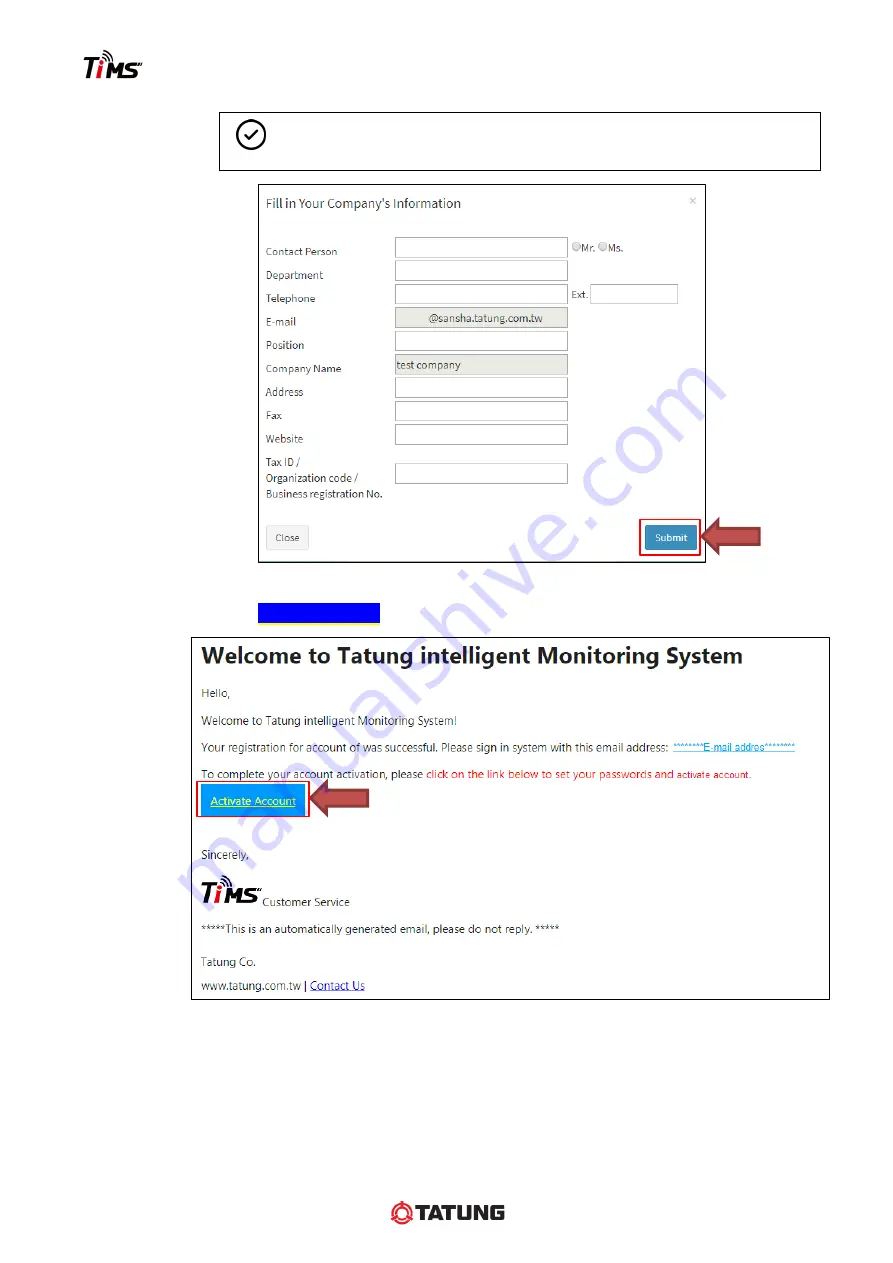
Step 4.  

Fill in the account information. 


NOTE 

All the items are required information. 


Step 5. 


Submit the form and 

receive the account activation mail. 

Step 6.  

Click


Activate Account

 linkage to connect the 

TiMS website

 and activate account.


Summary of Contents for TiMS

Page 1: ...Tatung intelligent Motor Sensor USER MANUAL Feb 20 2020 Version 2 1...

Page 2: ...ructions 9 2 6 Magnetic Control Switch 11 3 TiMS Communication Techniques 12 3 1 Communication Scheme 12 3 2 Wireless Communication Techniques 12 3 3 Sensor Monitoring Mode Functions 12 3 4 Data Stora...

Page 3: ...Website Address 32 7 2 Home Page 32 7 3 Device Status 32 7 4 TiMS Monitoring Information 33 7 5 Sensor Report Download 37 7 6 User Permission Account Setting 37 7 7 Monitoring Permission 38 7 8 Accoun...

Page 4: ...iate experience and with the authorization of the equipment owner This document and parts thereof must not be reproduced or copied without the express written permission of Tatung company and the cont...

Page 5: ...supplied product Tatung company will not take any liability for indirect or consequential damages such as loss of profit revenue losses and the like which may arise from the contract signed between t...

Page 6: ...ol Description Direct current Caution hot surface IP66 First characteristic numeral Degrees of protection against access to hazardous parts and against solid foreign objects Second characteristic nume...

Page 7: ...the return or collection for the proper disposal and recycling of the product contact Tatung company or send the TiMS to one of our authorized service centers Symbol Description The product cannot be...

Page 8: ...olt fixing Safety test IEC EN UL 61010 1 Fixing Dimension 88mm 3 47inch M4 2 Dimensions 76 x 62 x 23 mm IP Class IP66 2 99 x 2 44 x 0 91 inch Display Color LED Weight 0 22kg 0 49lbf BLE Switch Magneti...

Page 9: ...Measurement Periodic measurement interval Every 30 minutes Every 1 hour Measured data Motor Operating Status 3 axis Vibration RMS Motor Power Frequency Motor Skin Temperature Runtime Hour Residual Ba...

Page 10: ...c Including serial number 2 2 Sensor Serial Number Each sensor has five sets of unique identification numbers 1 Product serial number Product S N 2 Bluetooth connection name BLE Name 3 Sensor S N UUID...

Page 11: ...becomes green when a magnet put in the control position see Section 2 6 1 Warning alarm Yellow light twinkles every 12 seconds Danger alarm or LoRa transmission fail 1 Danger alarm Red light twinkles...

Page 12: ...4 4 PU plastic gloves for epoxy putty mixing 5 Cleaning objects such as cleaning naphtha rag fine sandpaper etc for cleaning the position to install the sensor on the motor frame 2 5 Sensor Installati...

Page 13: ...Fix the supporting plate and adjust by using level gage Wait for 24 hours for the epoxy putty to become totally solid then stick thermal pad on hexagon socket bolt and fix the sensor onto the supporti...

Page 14: ...position for 3 seconds the LED green light will flash 3 times and then enable the Bluetooth function Continuously bright green light flash Disable the Bluetooth signal Put the magnet at the control p...

Page 15: ...on user environment 2km 1 24mile include the influence of the building NOTE The distance is based on the test result of the Tatung factory outdoor environment by Multi Tech MTCDTIP LoRa gateway Becaus...

Page 16: ...limited by the LoRa communication architecture and not real time modification delay time may be several hours 4 After using the App via Bluetooth the Bluetooth radio signal of the sensor will disable...

Page 17: ...ansmission function i e BLE version 4 0 at least ii Users must ensure that the mobile internet is connected during the App process 3 App Download Linkage iOS Android App download QR Code shown as Appe...

Page 18: ...an separate the monitoring and management duty Admin permission Customer can register a main account for a manager to control all sensors monitoring and setting User permission Customer can register a...

Page 19: ...all TiMS App Sign in Account Go into TiMS Devices List please make sure the Internet Bluetooth function is working First time use Download history data or manual trigger status scan and vibration anal...

Page 20: ...User Manual English version _V2 0 17 5 2 Register TiMS Member Account Step 1 Open the TiMS website https tatungmotor azurewebsites net Step 2 Click the Register icon to sign up for the member account...

Page 21: ...is the same as Account Password password must be set with at least 8 characters NOTE I agree to Privacy policy and I agree to TiMS terms of service must be checked CAUTION User shall keep the account...

Page 22: ...9 Step 4 Fill in the account information NOTE All the items are required information Step 5 Submit the form and receive the account activation mail Step 6 Click Activate Account linkage to connect the...

Page 23: ...nu icon Step 3 Click Register Sensor Step 4 Key in the sensor serial numbers shown on the product and register it In sensor package On the sensor shell side When the sensor registered successfully it...

Page 24: ...ay s Step 4 Key in the Gateway serial numbers shown on the gateway package box or gateway and register it Tatung GWsn TiMLG xxxxxxxx Setting Web http 192 168 2 1 Register key XXXXXXXXXXXX Username adm...

Page 25: ...es and tablets to download the Tatung iMotor Sensor App and install it NOTE iOS Android App download QR Code shown as Appendix II Step 6 Enable the Internet network such as wi fi and data network and...

Page 26: ...process While TiMS App in process the network connection should be assured Finger icon means click position For the initial use of the sensor it will enter the Motor Information setting page at the be...

Page 27: ...not Step 4 Click the sensor in blue color to connect it via Bluetooth and agree to set the initial monitoring parameters For the initial use of the sensor it will show the Monitoring Setting page aut...

Page 28: ...lert memory and flash LED alert lights Only in Bluetooth connection status the function icon shows the bright blue or white block user can trigger the sensor instant real time functions such as measur...

Page 29: ...e used to test the LoRa connection distance between sensor and gateway Step 6 If user wants to know the cloud upload result please click Test Data Upload Result refresh icon When the upload time is up...

Page 30: ...p the default display list all the sensors belong to the user account Name in blue indicates the sensor which the Bluetooth signal is within the reachable range Click one to connect the sensor install...

Page 31: ...ist and second name connection time or BLE address Sort by is according to App connection time sensor name and received signal strength sensor distance 2 nd NAME SHOW select to display BLE Address ico...

Page 32: ...connection status ON BLE Mode shows the latest instant measurement data uploaded from App ON LoRa Mode shows the latest monitored data uploaded from Gateway If the measured data are abnormal the data...

Page 33: ...ON Warning Status Danger Status Graph display Temperature left ordinate 3 axis Vibration right ordinate Motor Status Background color Pinch or spread the screen with 2 fingers to zoom in or out the h...

Page 34: ...aintenance time Manual Vibration FFT Analysis In Bluetooth connection status user can click it to enter the analysis page and trigger instant vibration analysis Otherwise it will show the latest manua...

Page 35: ...ng Website Functions 7 7 1 Website Address https tatungmotor azurewebsites net 7 2 Home Page Account sign in and register 7 3 Device Status First page displays all the device equipment s latest status...

Page 36: ...7 4 TiMS Monitoring Information 1 Instant Status i Motor Brief Information ii Latest Monitoring Information the same as that shown in App iii History Graph the display area can be changed and adjuste...

Page 37: ...User Manual English version _V2 0 34 2 Alerts list Vibration analysis data Regular Maintenance Click Vib Analysis Data to check vibration analysis result uploaded from App...

Page 38: ...User Manual English version _V2 0 35 3 Equipment Information User can modify the motor information on this page or App...

Page 39: ...e NOTE After the LoRa alert setting the setting function will be locked until the sensor receives the command and responds to the setting result LoRa alert setting function is limited by the LoRa comm...

Page 40: ...user can add modify and delete the User permission account in this page The account administrator just needs to key in the E mail of the user and assign the sensor s to the account After receiving ac...

Page 41: ...English version _V2 0 38 7 7 Monitoring Permission Users can enable or disable the alert notification function on this page 7 8 Account Information Users can see and modify the account information on...

Page 42: ...User Manual English version _V2 0 39 7 9 Password Change Users can change account password on this page 7 10 Display Settings Users can change display language or unit by click this icon...

Page 43: ...User Manual English version _V2 0 40 Appendix I Epoxy Putty User Guide...

Page 44: ...User Manual English version _V2 0 41 Appendix II TiMS Website Address TiMs App Download QR Code 1 TiMS website https tatungmotor azurewebsites net 2 for iOS system 3 for Android system...

Page 45: ...nsulation class Coil temperature Warning Danger Class B 120 50 122 60 140 Class E 130 50 122 60 140 Class F 155 60 140 70 158 Class H 180 85 185 95 203 iii Abnormal vibration setting App will automati...

Page 46: ...ata Factory Default NA Light Grey Temp Abnormal Temperature Temp Temp Yellow Red Vib X Abnormal X axis Vibration Vib X Vib X Yellow Red Vib Y Abnormal Y axis Vibration Vib Y Vib Y Yellow Red Vib Z Abn...

Page 47: ...lectric com Toll Free 800 828 8641 Web www tatungelectric com Tatung Electric GmbH Schlehenweg 1 29690 Schwarmstedt Essel Germany Tel 49 5071 9689155 Fax 49 5071 9689151 E mail D Sawischlewski tatunge...

Reviews: