background image

15

Marchesan Implementos e Máquinas Agrícolas “TATU” S.A.

PST PLUS

Assembly

Drawbar resting position

NOTE

After removing the component that fasten the drawbar (A), articulate it to the resting 

position using the lock (B) and fasten it using pins (C and D) and lock pin.

B

A

C

D

The components that were removed from the drawbar must remain near 

the equipment and in a place that is easy to access.

Summary of Contents for PST Plus

Page 1: ......

Page 2: ...Dealer Owner Firm Farm City State No of the Certificate of Guarantee Serial No Date Invoice No Product Notes IDENTIFICATION...

Page 3: ...es a single and continuous distribution in every row crop The amount of seeds and fertilizer is easily adjusted by changing the combination of the sprockets TRA Using the oscillating rubber wheels adj...

Page 4: ...of the row markers 23 Procedures before operating the planter 24 Spacing between row units Positioning the row units in the frame 25 Spacing tables 26 Procedures to change the spacing 27 to 30 Plannin...

Page 5: ...ow marker hydraulic circuit 54 Automatic reset of the rod 55 Wheel for fertilizer covering 56 Clutch electronic reset 57 TATU PM 100 monitor 58 9 Maintenance 59 to 65 Lubrication 59 Lubricate every 10...

Page 6: ...staff Only people who own a full knowledge of the tractor and equipment must operate them Marchesan is not responsible for any damage caused by accident on transporting incorrect utilization or inade...

Page 7: ...The instructions under this symbol refers to the safety of the operator or third parties therefore they should be carefully read and observed Be careful with the environment PST PLUS planter is simpl...

Page 8: ...kin or clothes Keep access and work places clean and free from oil and grease Risk of accidents Never transport the equipment on highways or paved roads during the night Avoid that the tractor wheels...

Page 9: ...come entangled in moving parts Never operate the equipment without its protective devices Be careful while hitching the tractor to the equipment Wear appropriate gloves to work near the disc blades Wh...

Page 10: ...r must be lifted and locked in a vertical position or it must be removed and fastened to the load Fasten the moving parts that may get loose and cause accidents Underpin the equipment wheels appropria...

Page 11: ...E R T N C I A W A R N I N G A D V E R T E N C I A Antes de accionar la sembradora observe si no hay personas o animales en el rea de acci n de los marcadores de l nea o debajo de la sembradora Coloque...

Page 12: ...03 03 3854 Hopper logo 05 03 03 3853 Lateral logo 05 03 03 3866 PST PLUS sticker 05 03 03 1565 05 03 03 1942 El lacre podr ser removido solamente por el propietario O lacre somente poder ser rompido...

Page 13: ...ponents 01 Frame 02 Drawbar 03 Stabilizer 04 Tractor hitch 05 Jack 06 Fertilizer row unit 07 Fertilizer hopper 08 Seed row unit 09 Seed hopper 10 Ladder 11 Mechanical row marker 12 Transmission set 13...

Page 14: ...00 3000 610 35 1676 50 60 5 4 1884 60 5 5 2096 70 7 7 4 3000 3300 1040 50 2192 60 60 7 5 2232 60 70 7 6 2604 60 70 7 7 2617 70 90 8 8 4 3150 3600 1470 50 2344 65 95 8 5 2556 8 6 2768 8 7 2980 8 8 3192...

Page 15: ...ound in the components box according to the instructions Place the tractor hitch D using a pin E and cotter pin Fasten the hose support F to the drawbar using a clamp G spring washers and nuts Assembl...

Page 16: ...fter assembling the drawbar assemble the extensor A to the frame and to the drawbar using the pins B and C and lock pins Extensor assembly Assembly The tractor hitch D has a device to lock it in an ho...

Page 17: ...tion NOTE After removing the component that fasten the drawbar A articulate it to the resting position using the lock B and fasten it using pins C and D and lock pin B A C D The components that were r...

Page 18: ...quinas Agr colas TATU S A PST PLUS Hydraulic circuit 5 7 or 8 row units Assembly Item Description Quantity 01 3 8 x 3600 TR TM hose 01 Pressure 02 3 8 x 3600 TR TM hose 01 Return 03 Male quick couple...

Page 19: ...nsor D to the arm A and fasten using bolts E Then fasten the row marker disc F to the extensor D using a spring washer and nut The row markers have a sincronized activation with the movements of the p...

Page 20: ...ble disc 15 x 15 oscillating depth gauge wheels press wheels in V shape and fertilizer row unit with unaligned double disc 15 x 15 Fertilizer position On the same row and below the seeds Minimum spaci...

Page 21: ...ing washers and nuts Couple the hopper D that has a quick locking E To avoid damages to the quick locking and seed disc locking never overtight the quick lock adjuster F and leave it facing the thread...

Page 22: ...hesan Implementos e M quinas Agr colas TATU S A PST PLUS Assembly After assembling the rear part of the row unit lock the depth control A using bolts B spring washers and nuts Row unit assembly rear p...

Page 23: ...part of the tractor 1 Hitch the drawbar to the tractor hitch bar placing the pin and r clip If necessary use the drawbar extensor arm third point to facilitate hitching Observe that the hitch bar mus...

Page 24: ...he third point of the extensor A To facilitate the use of the extensor activate the hydraulic cylinder to relieve the drawbar in the traction bar After hitching the planter totally lift the row units...

Page 25: ...the fasteners should allow the markers to have enough articulation to accompany the differences of the land during the work and sustain the same ones raised during the maneuvers The adjustment range...

Page 26: ...in operation for the first time during off season or after a long inactive period follow the instructions below 1 Move and lock the lever A to release the chain tightener 2 Displace the chain from th...

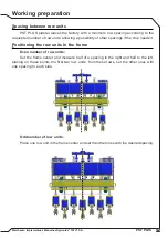
Page 27: ...these rows set the other ones with one spacing to each side Spacing between row units PST PLUS planter leaves the factory with a minimum row spacing according to the requested number of row units allo...

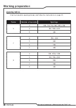
Page 28: ...tables Working preparation Check all possible spacings below and follow the instructions on page 25 Frame Number of row units Spacings 5 3 650 700 760 800 850 e 900 4 500 550 e 600 5 450 8 4 900 950...

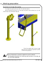
Page 29: ...r removing any row unit in the equipment Working preparation To change the spacing choose a flat firm and clean place Before lowering the jack A it is necessary to position them between the row units...

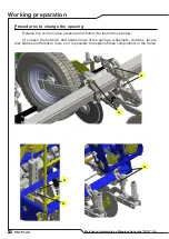
Page 30: ...Procedures to change the spacing Relieve the control valve pressure and follow the instructions below 1 Loosen the bolts A and fixation nuts of the springs wheelsets clutches levers disc blades and fe...

Page 31: ...g preparation Procedures to change the spacing 2 Remove the inner cotter pin B from the hexagonal axle that activates the row units 3 Loosen the bearing D bolts C 4 Remove the hexagonal axle s E that...

Page 32: ...ow unit and another So do not totally tighten a row unit at a time but gradually When switching between this nut tightening operation of a row unit and passing to another it is necessary to spin the h...

Page 33: ...that may take place during the cultivation cycle Also consider that during the plantation slippage or skidding of the planter tires can occur according to the local working conditions How to calculate...

Page 34: ...unt of seeds per meter per 10 meters and so on calculate how many linear meters of rows exist in a hectare in the desired spacing 0 85 m Example 10 000 11764 70 linear meters so 60 233 91 5 1198 0 85...

Page 35: ...er use List of standard seed plates in the planter NOTE ATTENTION Amount of graphite per kilogram of seed Planter distribution system Seeds treated with insecticide Small and round Big and round Flatt...

Page 36: ...ent and can be used in all places with one row of slots or holes i e corn in round shape soybean delinted cotton bean and others For the plate for corn with oblong holes use the pulley with 4 teeth wh...

Page 37: ...ft just release the counter nut and turn around the bolt to re lock In order to avoid damage to the spring and shafts never apply excessive torque when tightening NOTE SEMENTE SEEDS SEMILLAS 05 03 03...

Page 38: ...36 Marchesan Implementos e M quinas Agr colas TATU S A PST PLUS Seed distribution table 05 03 03 2997 Adjustments and operations...

Page 39: ...table from the previous page for a seed plate that has 24 holes 26 x 38 the amount of seeds per meter equals 2 23 Example Using the same transmission combination 26 x 38 but now using a seed plate wit...

Page 40: ...the values differ from the ones in the table Therefore it is always indispensable to make the practical distribution tests as indicated on page 41 IMPORTANT The cone bolts on the sprockets handling TR...

Page 41: ...pproximately 35 grams of granulated commercial fertilizer per turn The table B on the following page shows the obtained amount with the 1 coil pitch auger optional This auger transports approximately...

Page 42: ...10 000 m AVERAGE SPEED 06 Km h Grams in 50 m Per row SPROCKETS Drive shaft C Driven shaft D ROW SPACINGS mm 30x14 34x14 38x14 1786 2024 2263 PST PST SUPREMA COP COP SUPREMA ULTRA ULTRA SUPREMA ACTIVA...

Page 43: ...all tires Mark the distance for the test Fertilizer table example 50 linear meters Fill up the planter hoppers at least to the half and then travel some meters to completely fill the meterings before...

Page 44: ...on where all used data can be changed to one of your own interest Use the formula below which contains the following elements A Area to be fertilized m2 B Spacing between rows of the crop m C Amount o...

Page 45: ...n on the soil Unaligned double discs Oscillating disc blades no till The disc blades possesses lateral oscillation movements to follow the curves in the field During working do not perform sharp turns...

Page 46: ...ition Do not make sharp turns during working This act can cause damage to the row components Fertilizer depth and flotation range of the row units The brackets on the lower part of the rod adjust the...

Page 47: ...king pressure over the soil Opening the seed furrows The seed depth control is made individually through the gauge wheels A which possess adjustments through the handler B The graduation allows to adj...

Page 48: ...e lever that allows to operate in four positions and one neutral position 2 Adjust the angle between the press wheels vertex by the bolt and slot 3 Make the unalignment between the press wheels by the...

Page 49: ...ys use the same inflation in the tires Always use tires that have the same design and width to start planting If necessary put 3 4 of water in the tires and keep the same inflation Auxiliary depth con...

Page 50: ...latform Adjustments and operations The service platform is antiskid and wide to facilitate maintenance and to fill up the planter It is fastened to the planter frame using bolts B to offer a greater s...

Page 51: ...ctions The clutches can toggle the seed and fertilizer distribution to on or off automatically but can also be turned off manually to perform the finishings and it just uses half planter In order to d...

Page 52: ...nce C that should exist between the row marker disc and the center of the first seed row row in the planter extremity Example A Tractor trace center to the center of the first seed row 800 mm B Spacin...

Page 53: ...king angle The marker discs feature angle adjustment to facilitate the soil opening In order to do so loosen the nut and adjust as necessary A C WARNING BEFORE STARTING TO RAISE OR MOVE THE PLANTER CH...

Page 54: ...f the plantation Give special attention to the fertilizer position in the soil related to the seeds Carefully check the seed depth and the compaction pressure It is important to maintain a constant sp...

Page 55: ...198 Corn White 28 slots 11 5 x 8 5 mm 4 mm 05 03 01 6199 Corn Pumpkin 28 slots 11 x 8 mm 4 mm 05 03 01 6200 Corn Gray 28 holes 13 5 mm 4 mm 05 03 01 6201 Corn Pink 28 holes 13 mm 4 mm 05 03 01 6202 Co...

Page 56: ...ydraulic circuit 01 02 03 02 03 04 05 06 Item Model with 5 7 or 8 rows Qty 01 HBM complete sequence valve 01 02 3 8 X 2900 TR TC hose 02 Return 03 3 8 X 2600 TR TC hose 02 Pressure 04 3 8 X 4000 TC TM...

Page 57: ...T PLUS Automatic reset of the rod The automatic reset rod A is used for irregular soils The bolt B adjusts the pressure on the rod spring To assemble the rod A fasten it on the arm of the fertilizer r...

Page 58: ...covering wheel set must be left NOTE H A B C E F G I D Assemble the covering wheel fastener A in the arm B Place the covering wheel C in the fastener A Put the arm B in the support D using the bracke...

Page 59: ...and panel A should be installed in a place that is easy to access for the tractor conductor For a bigger commodity we recommend installing the control panel A in the tractor cab thus facilitating the...

Page 60: ...ired Track seeds up to 16 row unit planters Easy and flexible settings password protected Display mode customizable by the user Audible and visual alarm to indicate flaws in the row units Keeps the in...

Page 61: ...ant quality with relation to its efficiency and purity avoiding the use of products contaminated by water earth and others Use medium consistency grease Remove the remainder old grease around the arti...

Page 62: ...60 Marchesan Implementos e M quinas Agr colas TATU S A PST PLUS Lubricate every 10 working hours Maintenance Lubricate the points shown above and all grease fittings as well ATTENTION...

Page 63: ...61 Marchesan Implementos e M quinas Agr colas TATU S A PST PLUS Lubricate the points shown above and all grease fittings as well ATTENTION Maintenance Lubricate every 50 working hours...

Page 64: ...by the frontal part of the metering Remove the grease fitting H from the rear part of the metering to release the other parts as shown in the illustration and replace the defective ones Assemble the...

Page 65: ...ngs should be reassembled with a good amount of lubricant The hubs with grease fittings should be lubricated until the new grease is visible The hubs with tapered roller bearings fastened by castle nu...

Page 66: ...t using the stanchions and parking stands Totally retreat the hydraulic cylinder to lift the tire from the soil It is not necessary to release all the clutch set just remove the bolt A and spring wash...

Page 67: ...ace Remove the extensor articulate the drawbar upwards and lock it Keep the planter properly supported and avoid the direct contact of the discs and tires with the soil Planter maintenance Torque tabl...

Page 68: ...66 Marchesan Implementos e M quinas Agr colas TATU S A PST PLUS Titanium Apollo Titanium Apollo...

Page 69: ...intenance to the farmer It is an easy to use equipment because it works as a seed plate It features several technologies in order to provide a greater security and an excellent planting to the farmer...

Page 70: ...es 05 03 01 8468 SOYBEAN 80 holes 05 03 01 8483 BEET ONION 32 holes 05 03 01 8496 SORGHUM 32 holes 05 03 01 8159 PEANUT 32 holes 05 03 01 8497 CANOLA 80 holes 05 03 01 8498 Optional seed plates TITANI...

Page 71: ...the seeds to remain organized in the seed plate holes Flex brush Remove the seeds that did not fall off by gravity Its contact with the seeds provide less friction and less damage to them It is possi...

Page 72: ...the lubricant capacity of the graphite so the seeds will turn to black but will not be lubricated Graphite powder is the last treatment that should be applied to the seeds and has the purpose to lubr...

Page 73: ...P Brazil Telephone 55 16 3382 8282 Fax 55 16 3382 3316 Sales 55 16 3382 1009 Parts 55 16 3382 8297 Exportation 55 16 3382 1003 e mail tatu marchesan com br www marchesan com br MARCHESAN S A reserves...

Page 74: ...72 Marchesan Implementos e M quinas Agr colas TATU S A PST PLUS Notes...

Reviews: