www.tasking.com
Device description
A
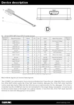
– 34-pin ERF8 MPC5xxx/SPC5 target pinout:
Signal Dir-
ection
Signal Description
Signal
Pin
Pin
Signal
Signal Description
Signal Dir-
ection
I
AGBT TX0_P
TX0+
1
2
Vref
Reference Voltage
I
I
AGBT TX0_N
TX0-
3
4
TCK
JTAG
O
Ground
GND
5
6
TMS
JTAG
O
I
AGBT TX1_P*
TX1+
7
8
TDI
JTAG
O
AGBT TX1_N*
TX1-
9
10
TDO
JTAG
I
Ground
GND
11
12
nJCOMP
JTAG TRST (optional)
O
AGBT TX2_P*
TX2+
13
14
NC
Not Connected
AGBT TX2_N*
TX2-
15
16
EVTI0
Nexus Event Input
O (not
used)
Ground
GND
17
18
EVTO0
Nexus Event Output
I
AGBT TX3_P*
TX3+
19
20
nPORESET
Power On Reset
O
AGBT TX3_N*
TX3-
21
22
nRESET
Reset
IO
Ground
GND
23
24
GND
Ground
Not Connected
NC
25
26
AGBT CLK_P
AGBT Clock
O
Not Connected
NC
27
28
AGBT CLK_N
AGBT Clock
O
Ground
GND
29
30
GND
Ground
Not Connected
NC
31
32
NC
Not Connected
Not Connected
NC
33
34
NC
Not Connected
34-pin ERF8 MPC5x/SPC5x target pinout
Blue colored signals are Aurora trace signals.
The JCOMP is an optional pin. Some microcontrollers don’t have this pin. Internally, this is actually
the JTAG TRST, which resets the JTAG TAP state machine. Because the JTAG TAP state machine
can be reset also by the TMS and the TCK, this pin is optional also for the debugger. If the micro-
controller has the JCOMP pin but it is not connected to the target debug connector, it must be set
to the non-active state in the target via a pull-up resistor. If not, then the JTAG TAP state machine
remains in reset and debugging is not possible.


