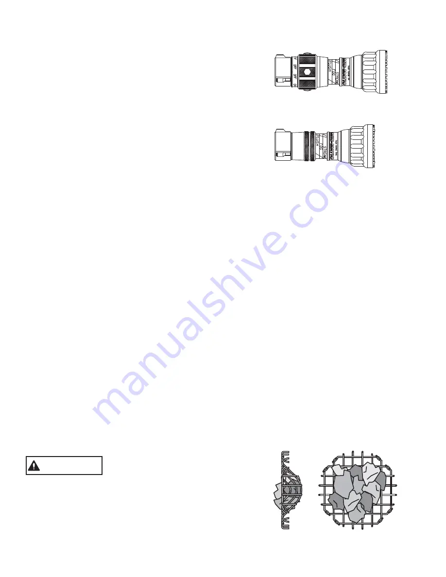
6
4.2.2 FLUSH CONTROL
Small debris passes through the gasket grabber and may get caught inside the nozzle. This trapped material will cause
poor stream quality, shortened reach and reduced flow. To remove this trapped debris the nozzle can be flushed as
follows; while still flowing water, turn the SHAPER counterclockwise past the full fog position (increased resistance will be
felt on the SHAPER as the nozzle goes into flush). This will open the nozzle allowing debris to pass through. Rotate the
SHAPER clockwise and out of flush to continue normal operation. During flush the nozzle reaction will decrease as the
pattern becomes wider and the pressure drops. The nozzle operator must be prepared for an increase of nozzle reaction
when returning the nozzle from the flush position to retain control of the nozzle.
Large amounts of debris can reduce
the flow of the nozzle resulting in an
ineffective flow. In the event of a
blockage it may be necessary to
retreat to a safe area, uncouple
nozzle and remove debris.
FIGURE 3 - GASKET GRABBER
WARNING
4.2 PATTERN AND FLUSH CONTROL
4.2.1 PATTERN CONTROL
TFT's ULTIMATIC, MID-MATIC and HANDLINE have full pattern control from straight stream to wide fog. Turning the
STREAM SHAPER clockwise (as seen from the operating position behind the nozzle) moves the SHAPER to the straight
stream position. Turning the SHAPER counterclockwise will result in an increasingly wider pattern.
Since the stream trim point varies with the flow, the stream should be "trimmed" after changing the flow to obtain the
straightest and farthest reaching stream. To properly trim a stream, first open the pattern to a narrow fog. Then close the
stream to parallel to give maximum reach.
The nozzle reaction is greatest when the shaper is in the straight stream position. The nozzle operator must be prepared
for a change in reaction as the pattern is changed.
NOTE: Turning the shaper further forward will cause stream crossover
and reduce the effective reach of the nozzle.
4.1.2 TWIST SHUTTOFF
4.1.3 TIP ONLY NOZZLES
On models that use a twist flow control. The valve is opened or
closed by rotating the valve ring. Rotating the ring clockwise (as
seen from the operating position behind the nozzle) closes the
valve, while counterclockwise rotation opens it. Detents are
provided at four intermediate positions and the position of the
valve is shown by the exposed valve position label.
Tip only nozzles have NO shut off valve contained within the
nozzle and
be used with a separate ball valve attached to
the nozzle.
MUST
LIN-030 November 14, 2008 Rev 10
©Copyright Task Force Tips, Inc. 2002-2008


