10
TASCAM DR-60DMKII
2 – Names and functions of parts
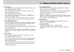
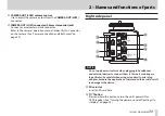
Left side panel
NOTE
Do not apply excessive force when plugging in external devices to
connect them to this unit or during use. In particular, be careful
when using a standard-to-mini plug adapter, because the appli-
cation of unintended force could result in damage to the device.
s
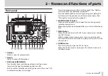
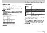
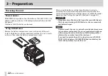
1/L connector (XLR/TRS)
These are balanced analog XLR/TRS combo jacks for microphone
and line level inputs.
XLR (1: GND, 2: HOT, 3: COLD)
TRS (Tip: HOT, Ring: COLD, Sleeve: GND)
d
3-4 connector (3.5mm stereo mini jack)
This TRS analog input jack can provide plug-in power.
TRS (Tip: HOT, Ring: COLD, Sleeve: GND)
f
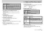
2/R connector (XLR/TRS)
These are balanced analog XLR/TRS combo jacks for microphone
and line level inputs.
XLR (1: GND, 2: HOT, 3: COLD)
TRS (Tip: HOT, Ring: COLD, Sleeve: GND)
CAUTION
•
Confirm that phantom power is OFF before connecting a line
level device to a 1/L connector or 2/R connector. If you connect
a line level device while phantom power is being supplied, that
device and this unit could be damaged.
•
When using a condenser microphone, before connecting to and
disconnecting from a 1/L connector or 2/R connector, confirm
that the phantom power for that jack is OFF. If you connect or
disconnect a mic while phantom power is being supplied, that
mic and this unit could be damaged.
•
Do not connect an unbalanced dynamic mic to an XLR connector
when phantom power is being supplied. Doing so could damage
that mic and this unit.
g
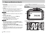
CAMERA IN connector (3.5mm stereo mini jack)
Connect to the audio output of a camera.
Refer to the camera’s operation manual to identify this connector
on the camera. (See “Camera connection and attachment” on
h
REMOTE connector (2.5mm TRS jack)
Connect a TASCAM RC-3F footswitch or TASCAM RC-10 wired
remote control (both sold separately) here to enable remote
starting and stopping of playback and other functions. (See “11 –

