


14
Appendix C: SW•10 Specifi cations
AC Power Requirements
US:
120 VAC, 60 Hz
Europe:
240 VAC, 50 Hz
Korea (AC Power Select at 230 V):
220 VAC, 60 Hz
Japan (AC Power Select at 115 V):
100 VAC, 50/60 Hz
AC Connector:
2-pin IEC 250 VAC, 16 A male
Fuse:
115 VAC: T 1.6 A/250 V
230 VAC: T 800 mA/250 V
*Power Consumption: 80 watts with music, loud mix
20 watts quiescent (idle)
Physical Dimensions and Weight
Enclosure:
0.625 in/16 mm thick MDF
Damping:
Adiabatic fi berfi ll
Dimensions:
Height:
11.8 in/300 mm
12.3 in/312 mm w/feet
Width:
12.0 in/295 mm
Depth:
12.4 in/315 mm
Weight:
28 lb/12.7 kg
Disclaimer
Since we are always striving to make our products
better by incorporating new and improved materials,
components, and manufacturing methods, we
reserve the right to change these specifi cations at
any time without notice.
Acoustic Performance
Free Field Frequency Response:
34
Hz
– 110 Hz (±3 dB)
Lower Cutoff Frequency:
–3 dB @ 34 Hz
Upper Cutoff Frequency:
–3 dB @ 110 Hz
Maximum SPL @ 1 meter, 7.5 dBu into both
Balanced Inputs:
103 dB SPL @ 1m
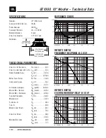
Transducer
Low Frequency Driver:
10 in/254 mm woofer with steel frame,
dual voice coil, and paper cone
Amplifi ers
Rated Power:
120 watts rms into a 4 ohm load
(60 watts rms x 2)
Burst Power:
270 watts rms into a 4 ohm load
(135 watts rms x 2)
Slew Rate:
> 15 V/µs
Distortion (THD, SMPTE IMD, DIM 100):
<
0.03%
Signal-to-Noise Ratio:
> 110 dB, 20 Hz to 20 kHz,
A-weighted, referenced to 60 watts
into 4 ohms
Type:
Monolithic IC, Class AB
Electronic Crossover
Crossover Type:
24 dB/octave Linkwitz-Riley
Crossover Frequency: Variable, 55 Hz to 110 Hz
Input Impedance:
20 k
Ω
, balanced bridging;
10
k
Ω
unbalanced
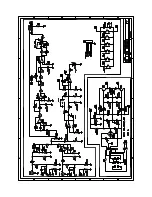
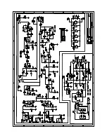
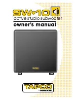
SW•10 Block Diagram
2
3
1
RIGHT
LINE INPUT
2
3
1
LEFT/MONO
LINE INPUT
CROSSOVER
FREQ
CROSSOVER
FREQ
55Hz-110Hz
24 dB/OCT LINKWITZ-RILEY
CENTER POSITION (80Hz)
2
3
1
LEFT/MONO
LINE OUTPUT
2
3
1
RIGHT
LINE OUTPUT
POLARITY
POWER
AMPLIFIER
INPUT
SENSITIVITY
(CW = THX)
180º
0º (THX)
PEAK POWER LIMITER
FAST ATTACK/SLOW RELEASE
+HI VDC
–HI VDC
SUBWOOFER
+
–
HI VDC
+
–
LO VDC
TOROIDAL POWER
TRANSFORMER
POWER
LED
TAPCO
SW•10
BLOCK DIAGRAM
09.15.04
115V
↔
230V
FUSE
POWER
AC SELECT
1
2
3
4
5
6
7
2
8
“Mackie.” and “TAPCO” are registered
trademarks of LOUD Technologies Inc. All other
brand names mentioned are trademarks or
registered trademarks of their respective holders,
and are hereby acknowledged.
©2004 LOUD Technologies Inc.
All Rights Reserved.
Summary of Contents for SW-10
Page 1: ...active studio subwoofer...