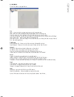
Tannoy Qflex User Manual Download Page 31

Buttons

Buttons generally have two states; depressed (active) and non-depressed (inactive). Generally, the button will apply the 

condition that is labelled when it is depressed. The space bar may be used to activate a button which is in focus.

Radio buttons

These are laid out in mutually exclusive groups to select one of a number of options. Press the radio button to select it, 

which will cause any other button in the group to be deselected. Once a control in the group is highlighted, the PGUP, 

PGDWN and Arrow keys may also be used to change the selection.
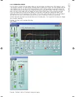
Faders

Faders provide a linearly traversing button, which may be dragged using a pressed mouse to adjust the value. These 

sometimes also have an associated value box for showing the numerical value of the parameter. Once the control is 

highlighted, the PGUP and PGDWN keys may be used for coarse adjustment, and the Arrow keys or the mouse wheel 

may be used to for fine adjustment.

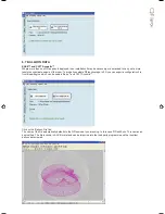
8.17  FILTER RESPONSE PANELS

Some panels provide a graphical representation of the response of one or more of the filters/equalisers in the device. 

These will usually consist of coloured semi-transparent filled areas representing individual filters, overlaid with a white 

curve line representing the overall response of a bank of filters/equaliser sections.

When the associated filter parameters are adjusted, you will see the curves responding so they always show the current 

response.

It will usually be possible to ‘drag’ the filter parameters with the computer mouse directly on the Response Panel. If you 

click anywhere in a Response Panel, you will see a set of ‘drag handles’ appear at the apexes of the individual filter 

response curves. These handles will usually have the same colour as the filter they relate to, and carry a number or letter 

to assist identification.

To change a filter parameter, place the mouse pointer over the drag handle, then press and hold the left mouse button 

while moving the mouse (vertically to change the filter gain, and horizontally to change the filter frequency). The filter 

With/Slope/Order may be adjusted either using the mouse wheel, or by holding the keyboard shift key whilst dragging the 

handle vertically.

The keyboard may also be used (see 

Keyboard Shortcuts).

Copy Graphics

To assist in preparing documentation etc, any response panel may be copied (to the Windows clipboard) by right-clicking 

on the panel and selecting Copy Image to Clipboard. The bitmap image may then be pasted into another application 

(such as word-processing), usually by selecting Edit>Paste in that application, or CTL+C.

Copy/Paste Settings

You can copy EQ settings from one channel to another on a given device, or copy EQ settings from one device to 

another. To do this simply right-click on the source panel (the one you want to copy from) and select Copy EQ Settings. 

Then on the destination response panel (the one you want to copy to), right-click and select Paste EQ Settings. You will 

be alerted to any problems such as the destination response panel not having enough EQ bands to reproduce the source 

EQ, or access to some or all of the bands being restricted due to security protection.

Summary of Contents for Qflex

Page 1: ...u s e r m a n u a l...

Page 2: ...such as radiators heat registers stoves or other apparatus including amplifiers that produce heat 9 Only use attachments accessories specified by the manufacturer 10 Refer all servicing to qualified s...

Page 3: ...circulation d air autour du panneau arri re Veiller ce qu il y ait un espace d au moins 100 mm tout autour du produit pour sa ventilation 5 Les l ments QFlex doivent tre assembl s ou d sassembl s uni...

Page 4: ...d Questions 6 9 Some Design Tips INSTALLING VNET SOFTWARE PODWARE 1 2 3 4 5 6 7 USING VNET SOFTWARE PODWARE 8 1 Overview 8 2 Layout 8 3 Menus 8 4 Toolbar 8 5 Communications 8 6 Launching a Panel 8 7 C...

Page 5: ...Bracket Mounting Centres QFlex 24 QFlex 32 10 5 QFlex 40 Assembly 10 6 Wall Bracket Mounting Centres QFlex 40 10 7 QFlex 48 Assembly 10 8 Wall Bracket Mounting Centres QFlex 48 SYSTEM CONNECTIVITY AUD...

Page 6: ...tion of QFlex products It is intended to be used in conjunction with the VNET BeamEngine Windows software packages Please read this user manual to get the optimum performance from your QFlex loudspeak...

Page 7: ...ules should be of version 7 7 Otherwise install the provided package in parallel 3 2 MATLAB RUNTIME LIBRARY MCR The MatLab Runtime Library MCR needs to be installed separately This MatLab Runtime Libr...

Page 8: ...e double click on the MCRInstaller_v77 exe The following window will appear Click on Run to start the installer Choose the setup language and click Ok to start the InstallShield wizard The InstallShie...

Page 9: ...Install to begin the Installation The installation will begin Due to the file size this may take some time Click Finish to complete the installation There is no need to start this programme as it resi...

Page 10: ...w will appear The QFlex Setup wizard will start click Next to continue Accept the terms of the licence agreement to continue with the installation Click Next to continue Approve the suggested file loc...

Page 11: ...Click on Install to begin the Installation Check Launch QFlex if you wish to begin using the software immediately Click Finish to complete the setup...

Page 12: ...ich the installer left on your desktop On the very first run of the program you will be prompted to select your preferred units of measurement These settings can be modified at any time in the menu op...

Page 13: ...ns Preferences Optimizer Tab Default Property Silent and Don t Care is explained in the menu The Master Beta function Master multiplication factor to apply to regularization factors beta given in glob...

Page 14: ...Which QFlex system you specify depends on a number of criteria Distance Farther areas you wish to reach will require a larger QFlex column Typically as a rule of thumb a QFlex 16 will be used to dist...

Page 15: ...e sound beam across the specified venue plane Normally the goal is to achieve an even SPL distribution across the whole venue plane Hint Where even coverage is required over large areas splitting the...

Page 16: ...s feature will allow the programme to factor for any inclinations in the mounting surface 12 The SPL scale can be referenced against the resultant SPL maps 13 Optimize Will generate the steering algor...

Page 17: ...ncreased to mach the SPL of the first venue plane Both beams can be independently manipulated in this way Additional venue planes can be added as necessary 2 By specifying a Silent venue plane in this...

Page 18: ...ss each venue plane is shown at 3a 6 6 SAVING STEERING FILE When you are ready to save your steering file click on the Steering File tab The name of the file automatically defaults to the QFlex model...

Page 19: ...evaluate QFlex coverage in 3D you can export a configuration file from BeamEngine which can be used in Ease and CATT Acoustic Click on the Balloon File tab The name of the file automatically defaults...

Page 20: ...SOME DESIGN TIPS In many applications a larger QFlex model at the front of the building will suffice A single QFlex model has the capability of generating a number of independent beams and creating ev...

Page 21: ...any existing versions 1 Having downloaded the software double click on the Setup exe icon The welcome screen will appear Click Next 2 Select your destination Folder Click Next 4 If you accept the lic...

Page 22: ...manipulate When devices are arranged in the main window their default representation is a Monicon an Icon which conveys basic monitoring status indication This Icon can usually then be opened up to t...

Page 23: ...communication with devices on the network Go Offline Stops communication with devices on the network Com Port Allows you to select which serial COM port you wish to use Launch Panels Launches the con...

Page 24: ...und See The Selected Device 8 5 COMMUNICATIONS PodWare communicates with a device using a serial COM port as a network connection This will usually be the COM port associated with the RS232 Serial por...

Page 25: ...n icon for the device will appear in the Panels node of the Tree Once the panel appears the application will take a few seconds while it copies the settings in the device to the control panel as indic...

Page 26: ...BAR The area in the status bar at the bottom right of the application window will indicate progress of some operations A coloured bar will extend to fill the extreme right hand box indicating progress...

Page 27: ...l bar with buttons for executing commonly used functions such as File Open File Save Locate and Help see ToolBar Main Control Panel The EQ Delay tab allows you to adjust the cabinet equalisation High...

Page 28: ...a to clipboard The data could then be pasted into a spreadsheet for further analysis Your dealer may ask you to do this is you have experienced a problem Note that in addition to showing amplifier pro...

Page 29: ...d by the beam design software will be for a given box The box number will usually be appended to the name of the file The number of each box is shown to the right of the device name in the Monicon It...

Page 30: ...on in focus You can bring a control into focus either by tabbing to it using the Tab key or by clicking on it with the mouse Focus is often shown as a dotted rectangle around part of the control or by...

Page 31: ...arameters with the computer mouse directly on the Response Panel If you click anywhere in a Response Panel you will see a set of drag handles appear at the apexes of the individual filter response cur...

Page 32: ...t the steering data will be overwritten PodWare will always try to protect your data warning you if you are attempting an action that could cause loss of data 8 20 LOADING FACTORY SETTINGS Using the F...

Page 33: ...as the edited mode will changes you make be heard Note however that if you make adjustments on the control panel when the active mode is different to the edit mode the settings are changed and stored...

Page 34: ...Input A muted...

Page 35: ...ture is activated in PodWare This allows you to confirm which control panel in PodWare is dealing with which physical loudspeaker Summary of indication During Loudspeaker power up Indicator winks rapi...

Page 36: ...odel and Version in the Device Properties dialogue To update the firmware in a device see Menus or Device Context Menus At the bottom right hand side of the screen a blue bar will show the progress of...

Page 37: ...purchase If you have purchased a QFlex 8 or a QFlex 16 there are no connecting plates or other joining hardware Each QFlex carton is marked to show each modules position in the array QFlex modules mu...

Page 38: ...T command returning to operating mode either upon the detection of audio or a power up VNET command QFlex products have analog and AES audio inputs and use VNET for monitoring and control For mechanic...

Page 39: ...grub screws allow the QFlex to be locked at the desired horizontal angle Having the hinge points on either side of the QFlex column allow the loudspeaker to be rotated at 90 degrees to the mounting s...

Page 40: ...tted to the wall first When you are satisfied with the mounting locations fix the bracket to the wall using the instructions supplied with the bracket and ensuring that the installation complies with...

Page 41: ...t it into the female connector in the upper module Align the two columns together as shown below Having the hinge points on either side of the QFlex column allow the loudspeaker to be rotated at 90 de...

Page 42: ...tted to the wall first When you are satisfied with the mounting locations fix the bracket to the wall using the instructions supplied with the bracket and ensuring that the installation complies with...

Page 43: ...Take the flying RJ45 connector in the middle module and insert it into the RJ45 socket in the top module Take the flying AC mains connector in the middle module and insert it into the female connecto...

Page 44: ...d be fitted to the wall first When you are satisfied with the mounting locations fix the bracket to the wall using the instructions supplied with the bracket and ensuring that the installation complie...

Page 45: ...ert it into the RJ45 socket in the third module Take the flying AC mains connector in the second module and insert it into the female connector in the third module Take the flying RJ45 connector in th...

Page 46: ...fitted to the wall first When you are satisfied with the mounting locations fix the bracket to the wall using the instructions supplied with the bracket and ensuring that the installation complies wi...

Page 47: ...nagement in your installation The connectors will not be visible when installation is complete Connections are accessed by the removal of the lower rear access plate on a QFlex master which will requi...

Page 48: ...ONNECTIONS VNET in Link Interconnection between the network computer and the speakers is very straight forward using twisted pair cable and simple connectors The USB to VNET RS485 interface operates o...

Page 49: ...is therefore suggested that solid should be used for install applications while stranded is better suited to rental applications Cabinets can be daisy chained or linked in a star configuration or a c...

Page 50: ...domestic situations Mains power is to be supplied from a permanent hard wired feed The feed for each QFlex must be protected by a fuse or circuit breaker rated at no more than 10A It must be possible...

Page 51: ...mmed and selected by means of the Operating Mode control inputs Since input selection and input mixing may be automatically adjusted using Operating Modes this may be useful for emergency evacuation V...

Page 52: ...Type 1004 4 driver 7900 1076 Tweeter Array 7900 1077 Amplifier Master 8 Way 7900 1078 Amplifier Master 16 Way 7900 1079 Amplifier Slave 8 Way 7900 1080 Amplifier Slave 16 Way 7900 1081 Grille 8 Way 79...

Page 53: ...mn Height 840mm 33 744mm 29 3 1483mm 58 4 Column Width 171 5mm 6 7 171 5mm 6 7 171 5mm 6 7 Column Depth 150mm 5 9 150mm 5 9 150mm 5 9 Typical Application Distance 20m 66ft 25m 82ft 40m 131ft Sample Ra...

Page 54: ...grees 120 degrees 120 degrees Aiming Angle Limit 70 degrees 70 degrees 70 degrees LF Beam Control Limit 400Hz 250Hz 200Hz Maximum SPL 100ft 30m 100dB 100dB 101 5dB Column Height 1387mm 54 6 2127mm 83...

Page 55: ...ommitment is our after sales support which now incorporates our extended Limited Warranty In the event of any concern that is not addressed by this extended Limited Warranty we would ask you to contac...

Page 56: ...uous research and development The introduction of new materials or manufacturing methods will always equal or exceed the published specifications All specifications are subject to change without notic...

Reviews: