5
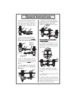
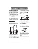
11. Reinstall second no.
6
, no.
3
, no.
5
and no.
2
onto no.
12
. Make necessary
adjustments to allow proper position-
ing of no.
1
.
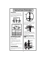
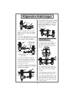
7. Insert no.
7
into no.
16
,
loosely
tighten
no.
13
onto threads by hand.
Do this for both hot and cold valves.
16
7
13
Hot Side
10. Reinstall no.
19
and no.
20
onto
no.
16
at top of sink.
Loosely tighten
by hand.
Do this for both sides.
(Make sure greased no.
8
is in place.)
Cold Side
4 (grooves
should face
downward)
4
(grooves should
face upward)
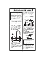
8. Insert no.
16
up through underside
of sink or lavatory and
fi
t no.
4
onto
no.
12
. (Make sure greased no.
6
is in
place.)
9.
Loosely tighten
no.
17
and no.
18
against bottom of sink.
Do this for
both sides.
16
12
18
17
4
6
16
6
8
4
6
3
2
5
12
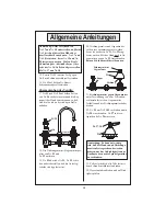
12. Tighten no.
10
and (top) no.
11
on underside of lavatory sink with a
wrench.
13. Tighten no.
2
on bottom of no.
12
with a wrench.
14. Tighten no.
17
and no.
18
on both
no.
16
’s underneath lavatory sink, also
tighten no.
19
and no.
20
on top side of
lavatory sink, with a wrench.
10
11
2
12
1
13
9
Final Assembly of Center Body
(No.12) Section:
20
19
.85 to .88
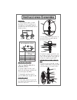
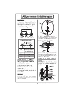
6. Remove no.
13
, no.
14
and no.
15
from no.
16
. Assemble the previous
items onto arm of no.
7
, as shown in
illustration below.
Both side valves.
7
13,14,15
16
General Instructions


