4
Installation:
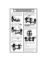
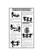
1. Turn off water supply and drain
lines. Drill (3) three holes in sink
or countertop where you are install-
ing faucet assembly. See illustration
below:
Center Body
2. Remove no.
2
from no.
12
by loos-
ening with a wrench. Disassemble all
parts from no.
1
.
2
Hot / Cold Side Valves
5. Remove no.
21/22
, no.
20
, and
no.
19
from no.
16
. (No.
17
and
no.
18
remain on no.
16
.)
12
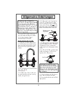
3. Install no.
12
(shank) through the
center hole in sink or deck. Reinstall
no.
10
and
fi
rst no.
11
as shown:
12
10
11
hand
tighten
9
6
4. Screw second no.
11
(about half
way up shank) and slide no.
9
and
no.
6
(greased) up onto bottom of
no.
12
shank.
greased
21/22
20
19
18
17
15
14
13
16
1
Installation: (Nozzle)
Note: Nozzle should be installed
fi
rst.
1. Apply Te
fl
on tape or pipe joint
compound to threaded end of
no.
32/33
.
2. Tighten no.
32/33
fi
rmly by hand
into no.
12
.
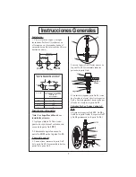
[2.5cm Ø]
[3.5cm Ø]
[3.5cm Ø]
[20 to 30cm]
[10 to 15cm]
1” Ø
1-3/8 Ø
1-3/8 Ø
4” to 6”
8” to 12”
HOT
HOT & COLD CENTER SECTIONS
CAN BE AT ANGLE
THEN FAUCET WILL
FIT X WITH STD. 1/4”
IPS CROSS PIPES
FURNISHED
X
Y
SPOUT
IF Y IS
1/2”
8”
1”
7-3/4”
1-1/2”
7-3/8”
2”
7”
COLD
General Instructions


